[0014] In order to have a clearer understanding of the technical features, objectives and effects of the present invention, specific embodiments of the present invention will now be described with reference to the accompanying drawings. Among them, the same parts are given the same reference numerals.
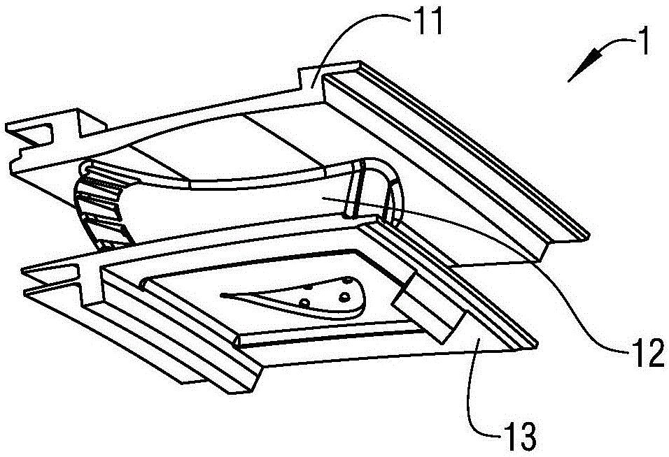
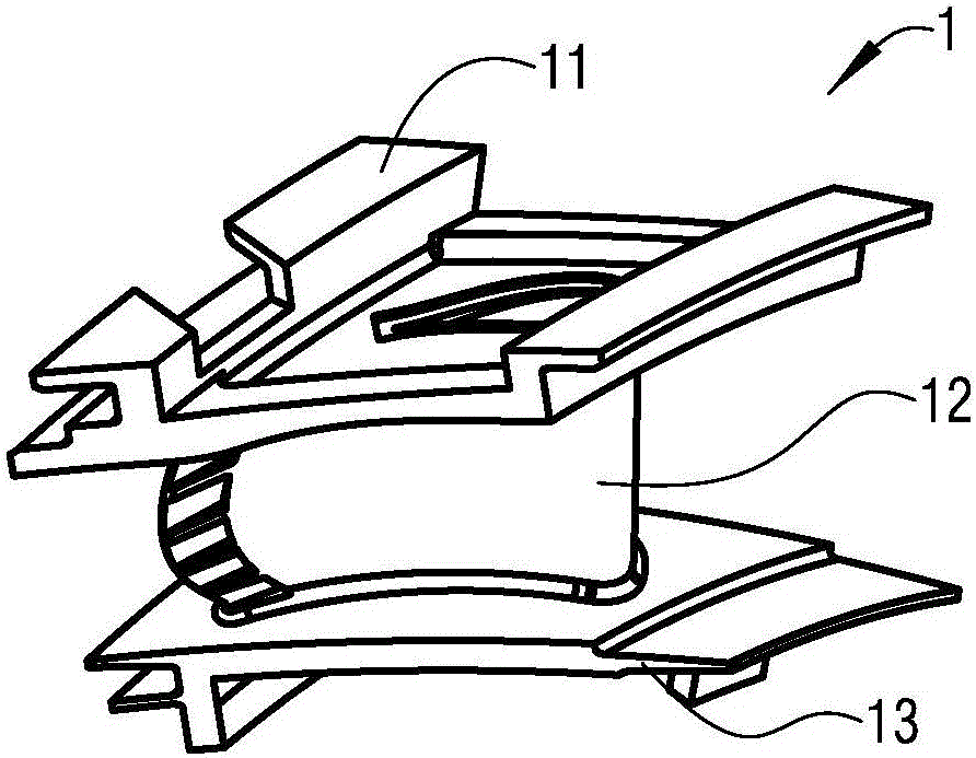
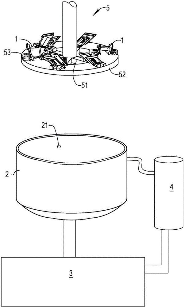
[0015] figure 1 It is a schematic diagram of the structure of the guide vane of a gas turbine engine; figure 2 For another angle figure 1 Schematic diagram of the structure of the guide vane; image 3 It is a schematic diagram of the structure principle of a low melting point alloy removal device for a blade cavity according to a specific embodiment of the present invention. See Figure 1-3 As shown, the present invention provides a device for removing low-melting-point alloys in a blade cavity. The blade 1 is composed of an outer edge plate 11, a blade body 12, and an inner edge plate 13, and the blade body 12 is provided with a trailing edge hole. 121, the outer edge plate 11 is provided with an outer edge cavity opening 111 in the middle, the inner edge plate 13 is provided with an inner edge cavity opening 131 in the middle, and the airfoil 12 is provided with the trailing edge hole 121 communicating with the The outer edge cavity port 111 and the cavity channel of the inner edge cavity port 131. The device includes an oil barrel 2. The bottom of the oil barrel 2 is connected to a cooling tank 3 through a pipe with a valve. 3 A heater 4 with an oil pump is connected through a pipeline, the side wall of the oil drum 2 is provided with a spray port 21, and the oil drum 2 is provided with a lifting and rotating mounting plate 5, the installation The disc 5 includes a mounting ring 52 connected by a supporting rib 51, and the mounting ring 52 is provided with multiple sets of mounting brackets 53 for clamping the blade 1; after the mounting brackets 53 clamp the blade 1, the The overall height of the mounting ring 52 and the blade 1 on it is 1/10 of the height of the oil drum 2;
[0016] The method of using the device provided by the present invention includes the following steps:
[0017] Step A: Use the mounting frame 53 to clamp a plurality of the blades 1 on the mounting plate 5 in the same circumferential direction, close the valve between the cooling tank 3 and the oil drum 2, and activate the heating The oil pump of the device 4 heats the oil delivered in the cooling tank 3 to 180°C and then sprays it into the oil drum 2 through the spray port 21. When the hot oil in the oil drum 2 reaches the oil drum When the height of 2 is 1/3, lower the mounting plate 5 so that the bottom surface of the mounting frame 53 is 1/10 of the height from the bottom of the oil drum 2; turn off the oil pump of the heater 4, and stop feeding the oil drum 2 Spray oil, and place the blade 1 in the hot oil in the oil drum 2 for 5-8 minutes;
[0018] A plurality of the blades 1 are clamped by the mounting bracket 53 on the mounting plate 5 in the same circumferential direction, that is, the trailing edge holes 121 of the blade 1 are all image 3 As shown, facing one direction.
[0019] The mounting bracket 53 can be a simple L-shaped lug adjusted by bolts, as long as it can clamp the blade 1. The space between the supporting ribs 51 can ensure that there is enough space for hot oil to flow up and down the mounting plate 5.
[0020] The heater 4 heats the oil to 180°C and then sprays it into the oil drum 2, so as to ensure that the temperature of the oil in the oil drum 2 can still be kept above 140°C after the heat loss during the spraying process .
[0021] After this step is completed, it can be ensured that the blades 1 are all immersed in hot oil. The immersion time of 5-8 minutes and the process of being sprayed when the mounting plate 5 descends can ensure that most of the low melting point alloy at the outlet is dissolved.
[0022] Step B: Open the valve between the cooling tank 3 and the oil drum 2 so that the hot oil dissolved with the hot melting point alloy flows into the cooling tank 3, and the cooling tank 3 cools the inflowing hot oil, and at the same time Start the oil pump of the heater 4, continue to inject oil into the oil drum 2, and make the mounting plate 5 start to rotate at a speed of 25-35 revolutions per minute. After rotating for 8-10 minutes, lift the The disk 5 is installed so that the bottom surface of the mounting frame 53 is raised above the oil barrel 2 to complete the removal of the low melting point alloy of the blade 1.
[0023] By adjusting the valve between the cooling tank 3 and the oil drum 2 and the oil pump of the heater 4, the amount of oil flowing from the oil drum 2 to the cooling tank 3 can be compared with that from the heater. 4 The amount of oil injected is the same, which can ensure that there is a sufficient amount of hot oil in the oil barrel 2 to dissolve the low melting point alloy.
[0024] The cooling tank 3 may be a metal tank surrounded by cooling and heat exchange pipes. After the hot oil dissolved with low melting point alloy flows into the cooling tank 3, it can be cooled to below the melting point temperature of the low melting point alloy. The low melting point alloy is cooled and solidified and separated, so that the oil pumped into the heater 4 does not contain low melting point alloy.
[0025] In a preferred embodiment, the cooling temperature of the cooling tank 3 is 80° C., which can ensure the separation of low melting point alloys on the one hand, and reduce the energy consumption of the heater 4 on the other hand.
[0026] The rotation speed of 20-30 revolutions per minute for 8-10 minutes can make the low melting point alloy in the blade 1 dissolve and escape from the inner cavity of the blade 1 under the action of centrifugal force.
[0027] In the process of raising the mounting plate 5, the hot oil sprayed from the spray port 21 can further affect the blade 1 when the mounting plate 5 rises from the oil surface to the outside of the oil drum 2. Clean up.
[0028] In a preferred embodiment, the rotation direction of the mounting plate 5 can be to keep the trailing edge hole 121 behind the rotation direction, which is beneficial to use the liquid flow to reduce the low melting point in the inner cavity of the blade 1 The alloy melts out.
[0029] The device for removing low-melting-point alloys in the blade cavity provided by the present invention effectively reduces the time for removing low-melting-point alloys on the one hand, and also effectively ensures that there is no residue in the blade cavity after the removal operation. In addition, low-melting-point alloys can be continuously performed in batch The alloy removal operation greatly improves work efficiency.
[0030] Those skilled in the art should understand that although the present invention has been described in the manner of multiple embodiments, not each embodiment only includes an independent technical solution. This description in the specification is only for clarity, and those skilled in the art should understand the specification as a whole, and regard the technical solutions involved in each embodiment as a way of combining them into different embodiments to understand the present invention. The scope of protection.
[0031] The foregoing descriptions are only illustrative specific embodiments of the present invention, and are not used to limit the scope of the present invention. Any equivalent changes, modifications and combinations made by any person skilled in the art without departing from the concept and principle of the present invention shall fall within the protection scope of the present invention.