Continuous flow system and method for coating substrates

Pending Publication Date: 2021-10-28
SINGULUS TECHNOLGIES AG
View PDF0 Cites 2 Cited by
  • Summary
  • Abstract
  • Description
  • Claims
  • Application Information

AI Technical Summary

Benefits of technology

[0072]The continuous machines and methods according to the invention allow for short introduction and/or removal times for substrate carriers with substrates. High-quality layers or laye

Problems solved by technology

Particularly in continuous machines which comprise a vacuum lock, the cycle times of the vacuum lock may significantly affect the throughput of the plant.
Conventional approaches to increase t

Method used


Image

  • Continuous flow system and method for coating substrates
  • Continuous flow system and method for coating substrates
  • Continuous flow system and method for coating substrates

Examples


Embodiment Construction

lass="d_n">[0093]While preferred or advantageous exemplary embodiments are described with reference to the drawings, additional or alternative configurations may be implemented in further exemplary embodiments. While, for instance, a substrate carrier for essentially rectangular substrates is illustrated in the figures, continuous machines and methods according to the invention may also be used for non-rectangular substrates, e.g., circular substrates. While a chamber of a vacuum lock is evacuated and vented via channels provided at opposing face sides in exemplary embodiments illustrated in some of the figures, the channels may also be disposed at the longitudinal sides of the chamber of the vacuum lock in further exemplary embodiments.

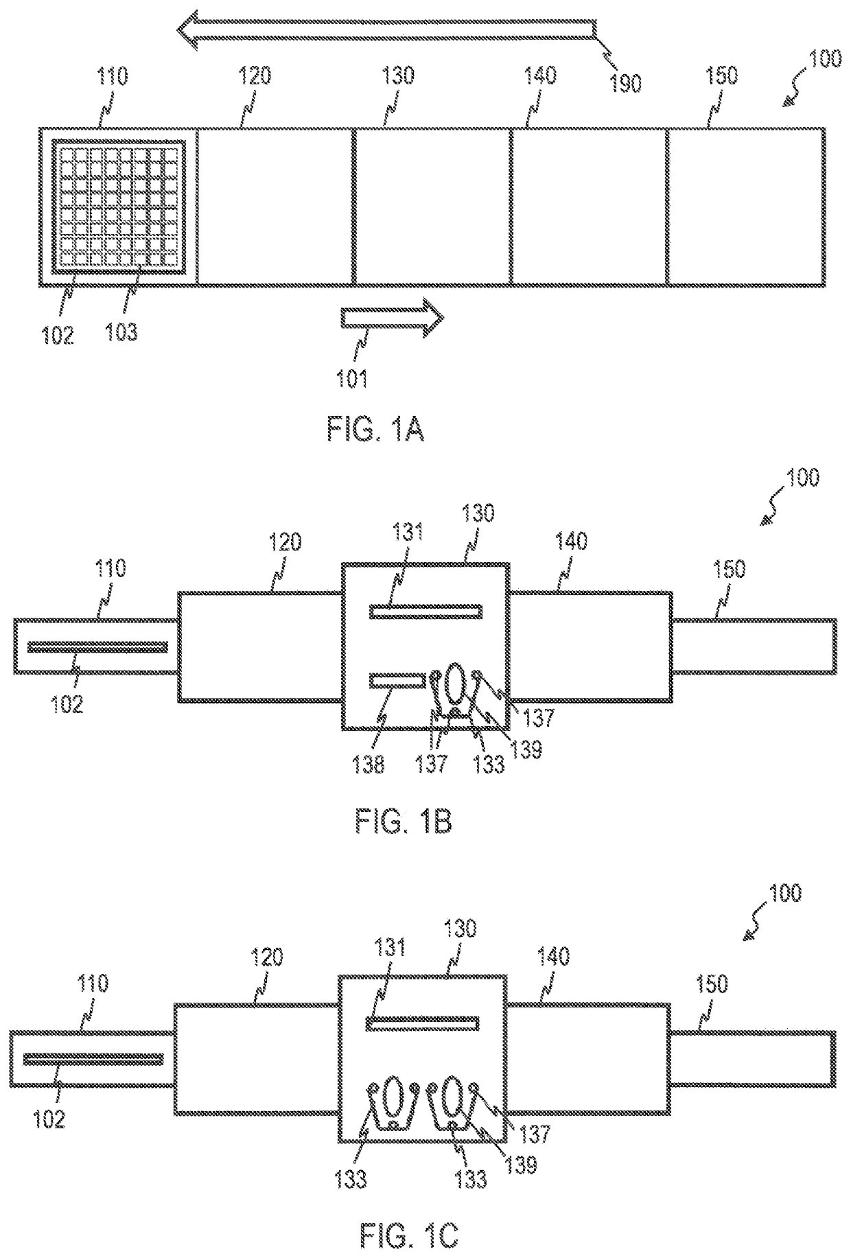
[0094]FIG. 1A shows a schematic illustration of a continuous machine 100 for treating substrates, particularly for coating substrates 103 in a top view. FIGS. 1B and 1C show schematic side views of exemplary embodiments of the continuous machine 100....


PUM

PropertyMeasurementUnit
Timeaaaaaaaaaa
Timeaaaaaaaaaa
Timeaaaaaaaaaa

Abstract

A continuous machine (100) for coating substrates (103) comprises a process module (130) and a vacuum lock (110, 150) for introducing the substrates (103) or removing the substrates (103). The vacuum lock (110, 150) comprises a chamber for receiving a substrate carrier (102) with a plurality of substrates (103) and a flow channel arrangement for evacuating and venting the chamber. The flow channel arrangement comprises a first channel for evacuating and venting the chamber and a second channel for evacuating and venting the chamber, wherein the first channel and the second channel are arranged at opposing sides of the chamber.

Description

TECHNICAL FIELD[0001]The present invention relates to continuous machines, particularly continuous vacuum plants, and methods, particularly vacuum methods, for coating substrates. The invention particularly relates to continuous machines configured for coating light substrates, particularly silicon wafers. The continuous machines and methods may be configured for the continuous coating of substrates.BACKGROUND[0002]Continuous machines for processing substrates are known from, e.g., EP 2 276 057 B1. Substrates are introduced into a vacuum process chamber by means of a substrate transport system and taken out again after having been processed. For this purpose, a horizontal substrate carrier against which the substrates rest along an area is used as a substrate transport system.[0003]US 2013 / 0031333 A1 discloses an installation for processing a plurality of substrates, said installation comprising locks.[0004]WO 2015 / 126439 discloses an apparatus and a method for passivating crystalli...

Claims


Application Information

Patent Timeline
IPC IPC(8): H01J37/32H01L31/18H01L21/677H01J37/34C23C14/56C23C16/54C23C16/50C23C14/34C23C14/06
CPCH01J37/32788H01L31/1804H01L21/67706H01L21/6776H01J37/32834H01J37/34H01L31/022425C23C14/568C23C16/54C23C16/50C23C14/3407C23C14/0652C23C14/566H01L21/67201H01L21/67173C23C16/345H01L21/6719H01L21/67017Y02P70/50Y02E10/547H01J2237/332
Inventor CORD, BERNHARDREISING, MICHAELSCHERGER, DIETERDIPPELL, TORSTENMAY, FRANKWOHLFART, PETERHOHN, OLIVER
Owner SINGULUS TECHNOLGIES AG
Why Eureka
Try Eureka