
Cabinet-type self-cleaning draught fan

A self-cleaning and fan technology, applied in mechanical equipment, non-variable-capacity pumps, machines/engines, etc., can solve the problems of endangering the user's health, attaching a lot of bacteria, and easily existing in many bacteria.

Active Publication Date: 2017-05-31
浙江理通风机科技股份有限公司
View PDF7 Cites 5 Cited by
  • Summary
  • Abstract
  • Description
  • Claims
  • Application Information

AI Technical Summary

Problems solved by technology

[0003] Chinese Patent Publication No. CN101392760A discloses a multi-blade centrifugal wind wheel, which includes an impeller core disk, a tire mounted in the impeller core disk, and blades installed in the tire; core plate, and then the motor drives the impeller core plate to rotate, and then the impeller core plate drives the blades to rotate. During the working process of the blades, a large amount of dust is easy to adhere to the blades, so that there are more bacteria in the wind passing through the blades, which seriously damages the User's health

Method used


Image

  • Cabinet-type self-cleaning draught fan
  • Cabinet-type self-cleaning draught fan
  • Cabinet-type self-cleaning draught fan

Examples


Embodiment Construction

[0036] The present invention will be described in further detail below in conjunction with the accompanying drawings.

[0037] This specific embodiment is only an explanation of the present invention, and it is not a limitation of the present invention. Those skilled in the art can make modifications to this embodiment without creative contribution as required after reading this specification, but as long as they are within the rights of the present invention All claims are protected by patent law.

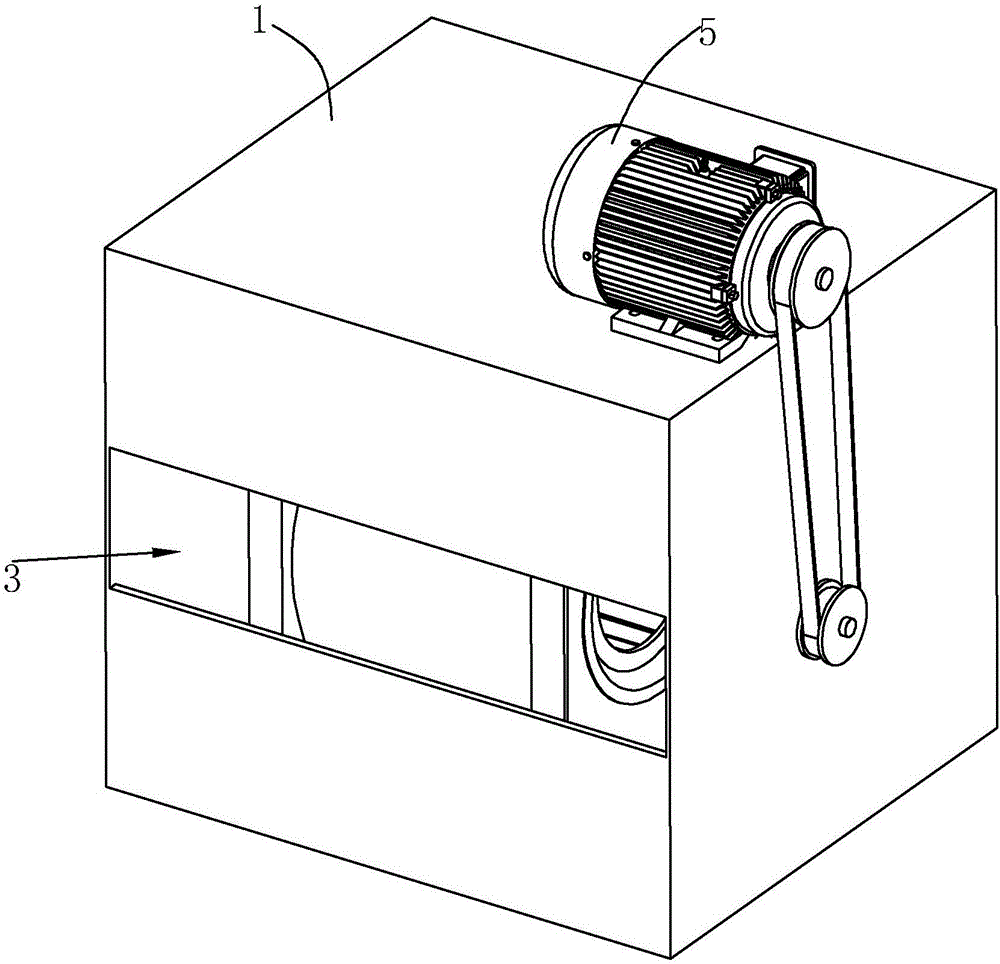
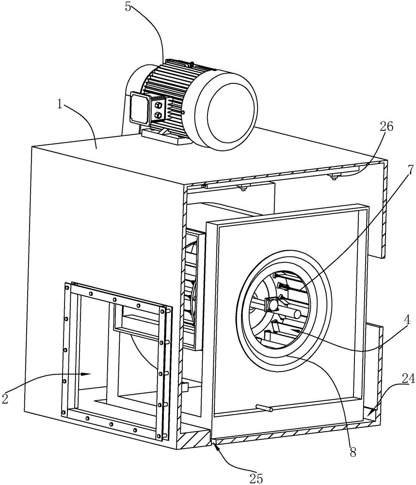
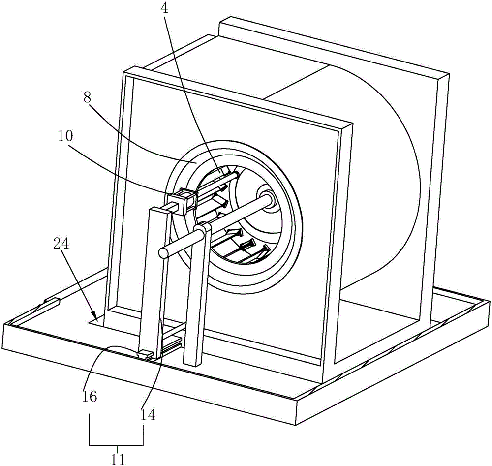
[0038] Such as figure 1 , 2 As shown, a cabinet-type self-cleaning fan includes a cabinet body 1, the front end of the cabinet body 1 is provided with an air outlet 2, and the rear end is provided with an air inlet port 3, and a fan assembly is provided in the cabinet body 1, and the fan assembly includes an impeller 4 With the motor 5 that drives the impeller 4 to rotate, during work, the motor 5 will drive the impeller 4 to rotate, and the impeller 4 will suck in the wind from...


PUM


Abstract

The invention discloses a cabinet-type self-cleaning draught fan comprising a cabinet body; an air inlet and an air outlet are formed in the cabinet body; a draught fan assembly comprising an impeller and a motor for driving the impeller to rotate is arranged in the cabinet body; the impeller comprises a wheel disc and blades; each of two ends of each blade is provided with an end ring; each blade is provided with a sliding sleeve for wiping the surface of the blade to be clean; the cabinet body is provided with a driving mechanism which is inserted to an inner ring of the end ring, is connected with each sliding sleeve and is used for driving the sliding sleeve to make reciprocating motion along the length direction of each blade; and a disconnecting part for disconnecting the driving mechanism and each sliding sleeve when the impeller rotates is arranged between the driving mechanism and the sliding sleeve. The technical scheme has the key points that due to the arrangement of the sliding sleeves, dust on the surfaces of the blades is cleaned because the driving mechanism drives the sliding sleeves to slide back and forth on the blades when the blades are required to be cleaned, and the condition that a great number of dust and bacteria on the blades are carried in the air passing through the blades because excessive dust exists on the blades is effectively avoided.

Description

technical field [0001] The invention relates to a cabinet type fan, in particular to a cabinet type self-cleaning fan. Background technique [0002] The cabinet centrifugal fan is used to convert the axial incoming airflow into a circumferential airflow, and the cabinet centrifugal fan impeller is an important part of the cabinet centrifugal fan. With the continuous improvement of aerodynamics, the development of impellers of various fans is adopting more novel designs to obtain higher efficiency, lower noise, and higher acoustic quality. [0003] Chinese Patent Publication No. CN101392760A discloses a multi-blade centrifugal wind wheel, which includes an impeller core disc, a tire mounted in the impeller core disc, and blades mounted in the tire; core plate, and then the motor drives the impeller core plate to rotate, and then the impeller core plate drives the blades to rotate. During the working process of the blades, a large amount of dust is easy to adhere to the blade...

Claims


Application Information

Patent Timeline
Patent Type & Authority Applications(China)
IPC IPC(8): F04D29/70
CPCF04D29/703
Inventor 张灵
Owner 浙江理通风机科技股份有限公司
Learn More