
Steam safety valve

A safety valve and steam technology, applied in the direction of safety valve, lifting valve, balance valve, etc., can solve the problems of easy deflection of the valve disc, affecting the sealing performance of the valve, and high center of gravity of the valve, so as to improve the sealing performance of the valve, increase the service life, The effect of avoiding destruction

Pending Publication Date: 2017-05-31
HARBIN HBC VALVE
View PDF8 Cites 1 Cited by
  • Summary
  • Abstract
  • Description
  • Claims
  • Application Information

AI Technical Summary

Problems solved by technology

[0003] The steam safety valve in the prior art mainly adopts a stroke control ring on the valve stem. After the valve is opened, the stroke control ring touches the cooler upwards to control the valve stroke; Independent exhaust chamber and adjusting sleeve to adjust the disc back chamber pressure, many parts and complicated valve structure
[0004] The existing technology is as described in the utility model patent CN201020150195.5. An independent back pressure adjustment mechanism is installed on a main steam safety valve to adjust the back pressure of the disc. There are many parts and complex structures, and the valve has a high center of gravity and poor shock resistance.
In addition, the outer circle of the disc sleeve does not have multiple balance grooves in the horizontal circumferential direction, and the disc is prone to deflection during opening and reseating, which affects the sealing performance of the valve.

Method used


Image

  • Steam safety valve
  • Steam safety valve
  • Steam safety valve

Examples


Embodiment Construction

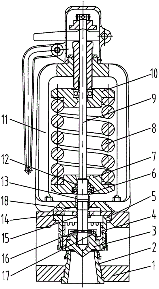
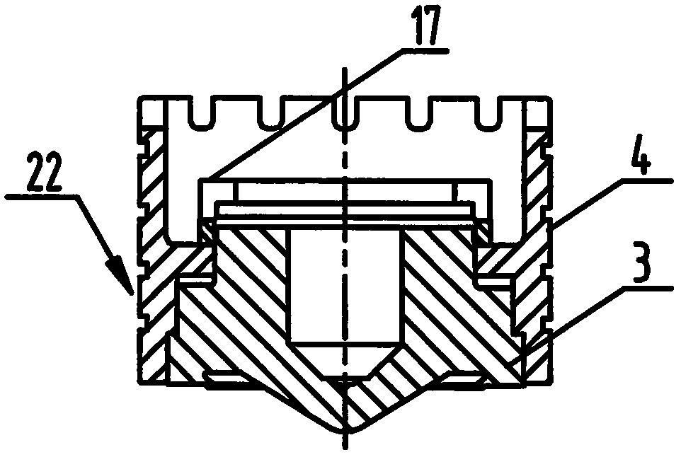
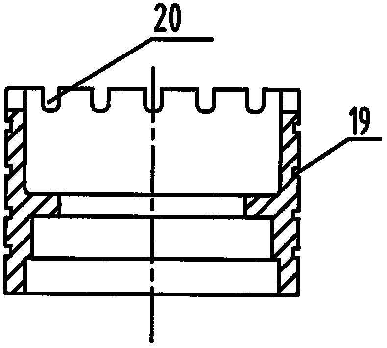
[0020] exist Figure 1 to Figure 5 In the shown embodiment, the valve body (1) is threadedly connected to the valve seat (2), and the valve disc (3) and the valve disc sleeve (4) are fixed by lock nuts (17) to form a valve disc sleeve assembly (22 ), and move up and down in the guide sleeve (5), the lock nut (17) has a bar-shaped groove (21), the pin shaft (16) passes through the valve stem (9) and is embedded in the bar-shaped groove (21), Prevent the valve clack (3) from rotating and affect the sealing performance of the valve.

[0021] The upper end of the guide sleeve (5) is embedded in the groove of the valve body (1), and the positioning plate (14) is placed above the guide sleeve (5), which is compressed by the spring cover (11). When the steam safety valve is opened to the full stroke, the upper end surface of the disc sleeve (4) pushes against the positioning plate (14) to limit the opening height, and the positioning sleeve (15) is set on the positioning plate (14) ...


PUM


Abstract

The invention relates to a steam safety valve, and belongs to the field of thermal power and nuclear power valves. The steam safety valve comprises a valve body, a valve seat, a valve clack, a valve clack sleeve, a guide sleeve, a belleville spring, a lower spring seat, a spring, a valve rod, an upper spring seat and a spring cover and has a backpressure cavity, balance groove, steam discharging groove and strip-shaped groove structure. The valve body is in threaded connection with the valve seat, the valve clack and the valve clack sleeve are fixed through a locking nut, and a valve clack sleeve assembly is formed and arranged in the guide sleeve and vertically moves. A locating plate is arranged in a groove of the valve body, and compressed by the spring cover. A pin shaft is arranged on the valve rod and embedded into a strip-shaped groove of the valve clack sleeve assembly. Compared with the prior art, according to the technical scheme, the steam safety valve has the beneficial effects that the locating plate is arranged, and a valve clack limiting and valve rod guide structure is simplified; a universal check block and a belleville spring buffer device are arranged on the valve rod, and the influence generated by great impacts when the valve returns to the seat is reduced; and the pin shaft is arranged on the valve rod, the valve clack can be prevented from rotating, and the performance of the valve is guaranteed.

Description

technical field [0001] The invention relates to a steam safety valve, which belongs to the field of thermal power and nuclear power valves. Background technique [0002] Safety valves are installed on thermal power, nuclear power units and pressure vessels, and are important equipment to protect the safety of units and containers. [0003] The steam safety valve in the prior art mainly adopts a stroke control ring on the valve stem. After the valve is opened, the stroke control ring touches the cooler upwards to control the valve stroke; The independent exhaust chamber and adjusting sleeve are used to adjust the pressure of the back cavity of the valve disc. There are many parts and the valve structure is complex. [0004] In the existing technology, as described in the utility model patent CN201020150195.5, an independent back pressure adjustment mechanism is installed on a main steam safety valve to adjust the back pressure of the disc. There are many parts and complex st...

Claims


Application Information

Patent Timeline
IPC IPC(8): F16K17/06F16K1/32
CPCF16K1/32F16K17/0433F16K17/06
Inventor 万胜军宋一新张红杰赵宇李大猛席立伟吕天时
Owner HARBIN HBC VALVE
Learn More