Compact light source switching device

A light source switching and compact technology, which is applied in the field of opto-mechanical, can solve the problems that there is no device for switching between LED light source and laser light source, it is not suitable for light portable equipment, and the switching mechanism is large in size. small effect

Active Publication Date: 2017-05-31
HARGLO APPLIED LASER TECH INST CO LTD
View PDF6 Cites 1 Cited by
  • Summary
  • Abstract
  • Description
  • Claims
  • Application Information

AI Technical Summary

Problems solved by technology

Most of the existing equipment on the market can only emit a single light source; a small number of switching devices with dual light sources are switched by different LEDs to emit no light source, and no device that can switch between LED light source and laser light source has been found.
[0003] Mo

Method used


Image

  • Compact light source switching device
  • Compact light source switching device
  • Compact light source switching device

Examples


Embodiment Construction

[0029] It should be noted that, in the case of no conflict, the embodiments of the present invention and the features in the embodiments can be combined with each other.

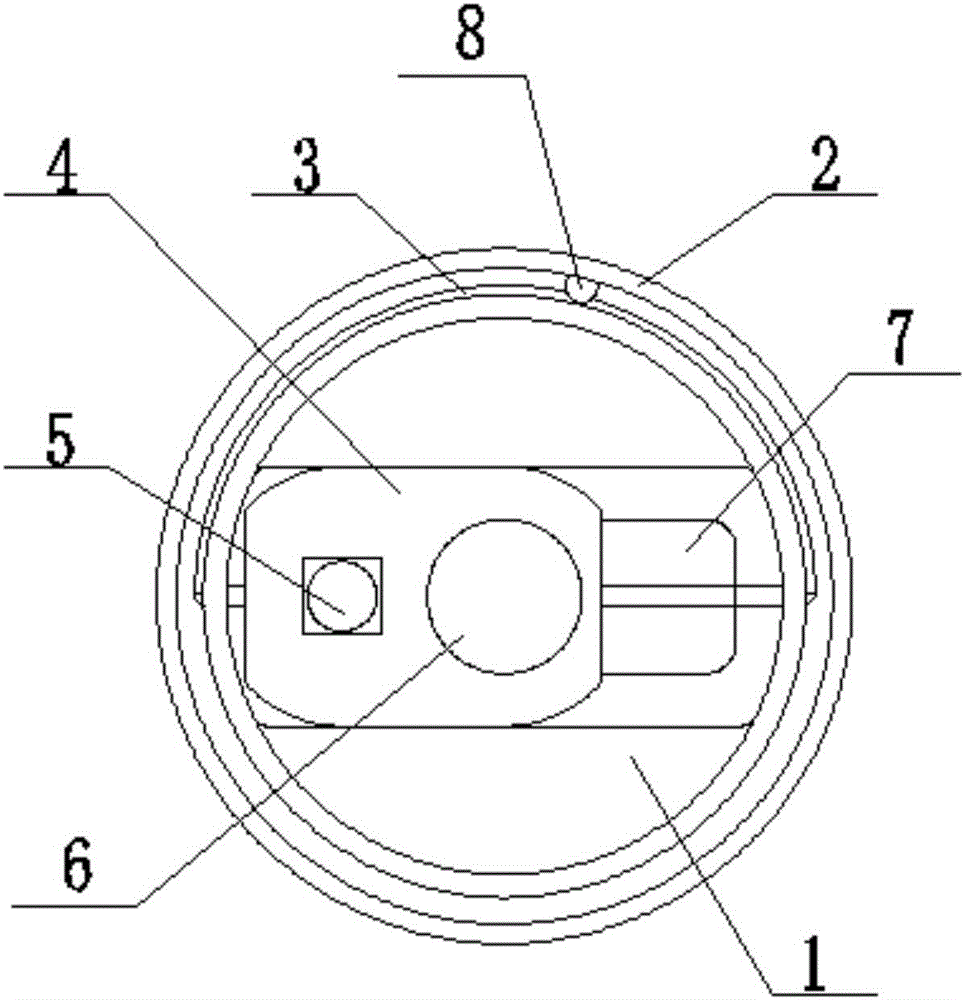
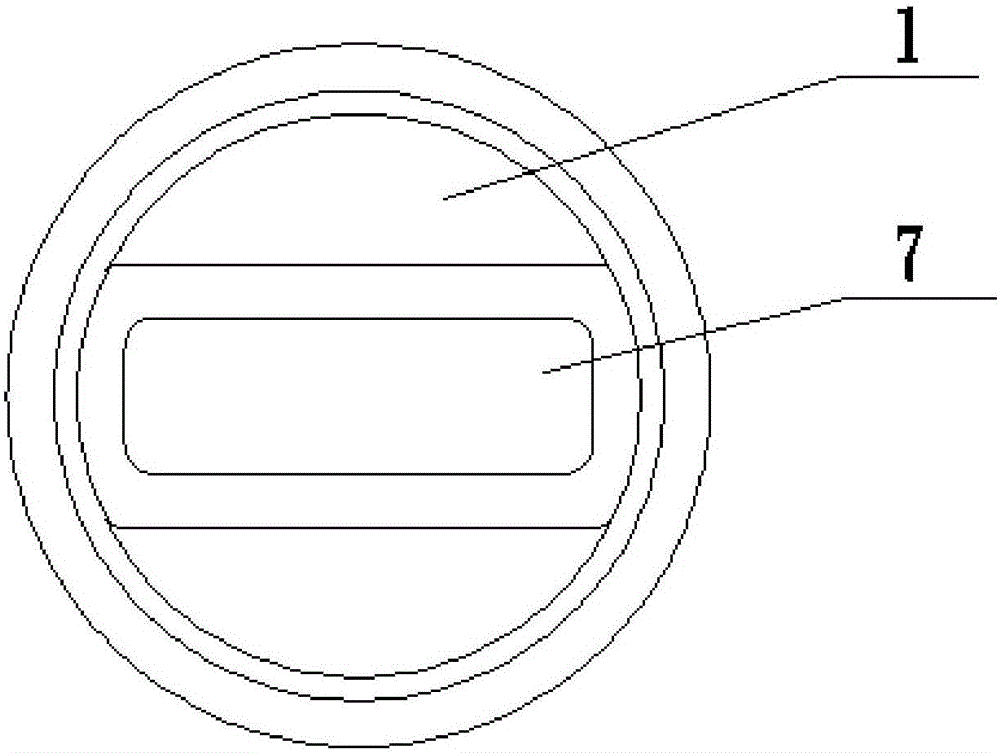
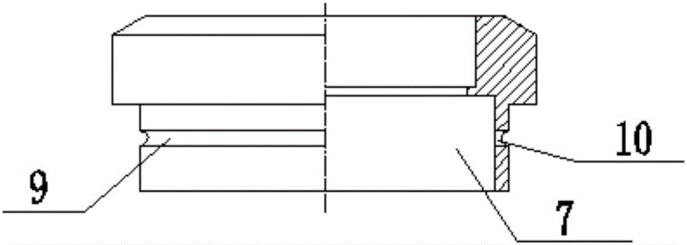
[0030] In describing the present invention, it should be understood that the terms "center", "longitudinal", "transverse", "upper", "lower", "front", "rear", "left", "right", " The orientations or positional relationships indicated by "vertical", "horizontal", "top", "bottom", "inner" and "outer" are based on the orientations or positional relationships shown in the drawings, and are only for the convenience of describing the present invention and Simplified descriptions, rather than indicating or implying that the device or element referred to must have a particular orientation, be constructed and operate in a particular orientation, and thus should not be construed as limiting the invention. In addition, the terms "first", "second", etc. are used for descriptive purposes only, and should not be understood ...


PUM


Abstract

The invention provides a compact light source switching device. The compact light source switching device comprises a base, a switching ring, a pulling rope, a heat sink and light sources, wherein a groove is formed in the base; the switching ring can rotate around the base; the pulling rope is connected to the two ends of the heat sink and fastened to the switching ring; and the heat sink is provided with the light sources and light transmission holes, can be provided with the multiple light sources or the multiple light source light transmission holes or can be provided with the multiple light sources and the multiple light source light transmission holes at the same time. The switching ring is rotated and drives the pulling rope to move, and the pulling rope drives the heat sink to slide, so that switching of the light sources is achieved. The compact light source switching device is compact in structure, reasonable in design, easy to assemble, convenient to realize, small in size and low in weight; the double-light-source switching function is achieved, and integration of various light source emitting mechanisms is also achieved; and the compact light source switching device is low in realizing cost, convenient and rapid in light source switching, long in service life, high in practicability and easy to apply and popularize.

Description

technical field [0001] The invention belongs to the field of optomechanical technology, and in particular relates to a compact light source switching device. Background technique [0002] Now the common light emitting equipment is mostly a single light source. Equipment with a single light source can no longer meet the needs of some special markets. For example, when on duty or hunting at night, green light and white light need to be used together. Most of the existing equipment on the market can only emit a single light source; a small number of switching devices with dual light sources are switched by different LEDs to emit no light source, and no device that can switch between LED light source and laser light source has been found. [0003] Most of the existing light source switching mechanisms have a rotating mechanism and use the cam principle to realize the switching, which makes the switching mechanism large in size, complicated in machining, and heavy, which is not ...

Claims


Application Information

Patent Timeline
IPC IPC(8): F21K9/20F21V29/70F21V19/04F21Y115/10F21Y115/30
CPCF21V29/70
Inventor 张鸿博樊仲维赵三军马有瑄
Owner HARGLO APPLIED LASER TECH INST CO LTD
Why Eureka
Try Eureka