Display device and assembling method thereof

A technology of a display device and an assembly method, which is applied in the directions of lighting devices, fixed lighting devices, components of lighting devices, etc., can solve the disadvantages of overall size reduction of display devices, narrow frame design, increased manufacturing costs, and bright lines on the edges of image images. and other problems, to achieve the effect of being conducive to the design of narrow frame, reducing the overall size, and solving the problem of bright lines

Inactive Publication Date: 2017-05-31
CORETRONIC
View PDF5 Cites 10 Cited by
  • Summary
  • Abstract
  • Description
  • Claims
  • Application Information

AI Technical Summary

Problems solved by technology

Under this configuration and assembly method, too many components such as the back plate and the plastic frame are not conducive to the overall size reduction and narrow frame design of the display device, and too many components will increase the manufacturing cost
[0003] In addition, if the frame of the display device is to be narrowed, the light beam emitted from the side of the backlight module is easy to emerge from the display area of ​​the display panel at a large angle, and the user can easily see the light emitted from the side of the display device at a direction of about 45 degrees. light beams, and the edge of the image screen of the display device is prone to the problem of bright lines

Method used


Image

  • Display device and assembling method thereof
  • Display device and assembling method thereof
  • Display device and assembling method thereof

Examples


Embodiment Construction

[0031] The foregoing and other technical contents, features and effects of the present invention will be clearly presented in the following detailed description of a preferred embodiment with reference to the accompanying drawings. The directional terms mentioned in the following embodiments, such as: up, down, left, right, front or back, etc., are only referring to the directions of the drawings. Accordingly, the directional terms are used to illustrate and not to limit the invention.

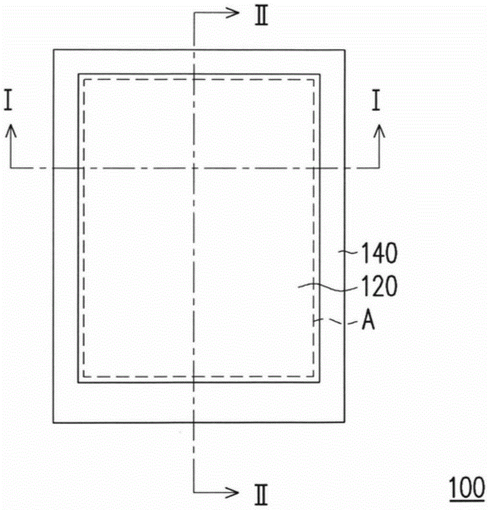
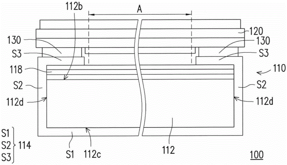
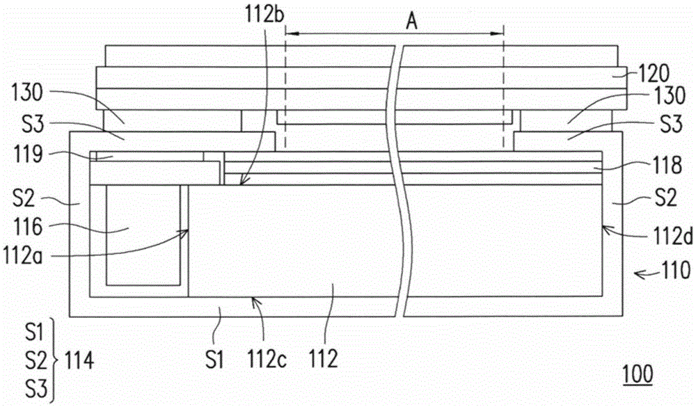
[0032] figure 1 It is a top view of a display device according to an embodiment of the present invention. figure 2 yes figure 1 A cross-sectional view of some components of the display device along the I-I line. image 3 yes figure 1 A cross-sectional view of some components of the display device along line II-II. In order to make the drawings more clear, figure 1 The housing 140 is not shown in the figure 2 and image 3 middle. Please refer to Figure 1 to Figure 3 , the display d...


PUM


Abstract

A display device comprises a backlight module, a display panel and a first glue layer. The backlight module comprises a light guiding plate, a flexible reflecting sheet and a light source. The light guiding plate is provided with a light incoming face, a light outgoing face, a back face and a plurality of side faces. The flexible reflecting sheet is provided with a first area segment and a plurality of second area segments. The back face of the light guiding plate leans against the first area segment; the second area segments are connected to the first area segment and are bent relative to the first area segment; and at least part of the second area segments cover the side faces of the light guiding plate correspondingly. The light source is arranged on the flexible reflecting sheet and is aligned with the light incoming face of the light guiding plate. The light outgoing face faces the display panel. The display panel and the backlight module adhere to each other through the first glue layer. The first glue layer is located between the display panel and the second area segments of the flexible reflecting sheet. The invention also discloses an assembling method of the display device. Thus, the display device can achieve the frame narrowing function.

Description

technical field [0001] The present invention relates to a display device and its assembly method, and in particular to a display device with a flexible reflective sheet and its assembly method. Background technique [0002] Benefiting from the progress of semiconductor components and display technology, electronic products continue to develop in the direction of miniaturization, multi-function and portability. Common portable electronic products include notebook computers, tablet computers and smart phones. Generally speaking, the electronic products have a display device for displaying pictures for users to watch, and generally a backplane and a plastic frame are arranged in the casing of the display device to support the backlight module and the display panel. Under this configuration and assembly method, too many components such as the back plate and the plastic frame are not conducive to the overall size reduction and narrow frame design of the display device, and too m...

Claims


Application Information

Patent Timeline
Patent Type & Authority Applications(China)
IPC IPC(8): F21S8/00F21V7/00F21V8/00F21V17/10
CPCF21S8/00F21V7/00F21V17/101
Inventor 郭家维
Owner CORETRONIC
Why Eureka
Try Eureka