Energy-saving stove with inductive fire-control pot frame and fire control method

A cooker and pot support technology, which is applied in the field of energy-saving cookers, can solve the problems that electronic sensors cannot continue to work stably, mechanical switches cannot be made fine and durable, frequent feeding or refueling operations, etc., to ensure continuous work without overheating and improve stability performance and safety, and the effect of securing the working temperature

Pending Publication Date: 2017-05-31
HUBEI ZHONGRUITIANHENG ENERGY SAVING TECH DEV
View PDF12 Cites 6 Cited by
  • Summary
  • Abstract
  • Description
  • Claims
  • Application Information

AI Technical Summary

Problems solved by technology

However, in practical applications, it is found that this method of setting the pressure sensor at the pot frame of the burner does not work well. It cannot work continuously and stably, and is easy to be damaged; mechanical switches cannot be made fine and durable
On the other hand, during the cooking process, it is very frequent for the chef to overturn the pot and temporarily remove it from the furnace mouth, temporarily put it aside for feeding or refueling operations, and it cannot be determined that the fire should be turned off just because the pot is temporarily removed. And re-ignition in the original way
Therefore, the current method of setting pressure sensors at the combustion port cannot achieve energy-saving effects well, and there is still a gap between practical application or long-term stable use

Method used


Image

  • Energy-saving stove with inductive fire-control pot frame and fire control method
  • Energy-saving stove with inductive fire-control pot frame and fire control method
  • Energy-saving stove with inductive fire-control pot frame and fire control method

Examples


Embodiment Construction

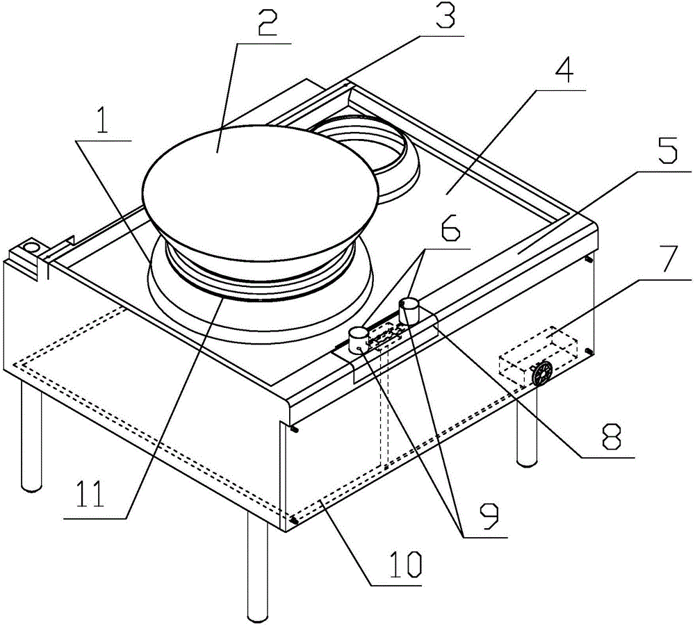
[0030] Below in conjunction with accompanying drawing and embodiment the present invention is further described: as figure 1 The shown energy-saving cooker with induction fire control pot support includes a hearth, a cooktop 4 and a fire control device 7. The fire control device is used for ignition start and fire control. On the basis of the most common cooker, a fire side pot support 8 and an electronically controlled Fire controller7.

[0031] The pot rack 8 by the fire is located on the edge of the operator side of the stove top 4, and is used for temporarily placing pots and utensils during the cooking process for adding or changing materials. close roasting. The pot stand 8 beside the fire is provided with supporting feet 6. In the embodiment, the toes of the supporting feet face upwards to support the pot. One to three supporting legs can be provided, and a sensing pot position is provided inside the supporting legs. Sensing facilities9.

[0032] The sensing facility...


PUM


Abstract

The invention relates to an energy-saving stove with an inductive fire-control pot frame and a fire control method. A fire-side pot frame for temporarily placing a pot in a cooking process is arranged on the edge of one side, close to an operator, of a cooking bench surface and is provided with support legs, and induction facilities for sensing the position of the pot are arranged in the support legs; and the induction facilities include a first pot position sensing facility and a second pot position sensing facility, the first pot position sensing facility is used for sensing the existence of the pot above a hearth, the second pot position sensing facility is used for sensing the existence of the pot on the fire-side pot frame, and the induction facilities are used for lighting furnace fire when sensing that the pot is placed on a stove hole and turning down or quenching the fire when the pot is taken away from the stove hole. A space between a stove cycle and the pot is closed, and fresh air is introduced to cool the fire-side pot frame and a fire controller. Based on the practicality, the inductive fire control and energy saving of the pot capable of stably working for a long time are truly realized, and the working stability and safety of a system are improved.

Description

technical field [0001] The invention relates to an energy-saving technology for a kitchen stove, in particular to an energy-saving stove with an induction-controlled hot pot rack. Background technique [0002] During the cooking process, the chef will often perform operations such as turning the pot upside down or adding and changing materials in the middle, and the pot is moved away from the furnace mouth more frequently, resulting in a reduction in the heating efficiency of the stove fire on the pot and a waste of energy. [0003] In order to save energy and strengthen firepower control, a new technology of setting a pot support with pressure sensing facilities on the combustion port has appeared in the prior art. When the pressure is significantly reduced, the fuel valve is turned off or reduced. However, in practical applications, it is found that this method of setting the pressure sensor at the pot frame of the burner does not work well. It cannot work continuously an...

Claims


Application Information

Patent Timeline
Patent Type & Authority Applications(China)
IPC IPC(8): F24C3/12F24C5/16
CPCF24C3/126F24C5/16Y02B40/00
Inventor 张跃虎
Owner HUBEI ZHONGRUITIANHENG ENERGY SAVING TECH DEV
Why Eureka
Try Eureka