Closed type heat-exchange hot water system utilizing intermittently supplied waste heat

A hot water system and closed-circuit technology, applied in the field of waste heat utilization hot water engineering, can solve the problems of energy waste, uneconomical, high energy consumption of standby energy, save investment and operating costs, better use comfort, and economical operation. energy saving effect

Active Publication Date: 2017-05-31
CMCU ENG
View PDF9 Cites 0 Cited by
  • Summary
  • Abstract
  • Description
  • Claims
  • Application Information

AI Technical Summary

Problems solved by technology

In the case of continuous supply of waste heat, the water temperature in the hot water storage tank can be kept within an appropriate range. However, when the supply of waste heat energy is stopped, the total amount of water used will increase with the extension of the water use time, and the replenishment of cold water will increase. Large-scale closed heat storage The outlet water temperature of the water tank drops. When the outlet water temperature cannot meet the user's water temperature requirements, the backup energy is activated. However, it takes a long time to adjust the water temperature in the large closed hot water storage tank, which affects the user's comfort.
If you blindly increase the maximum power of the backup energy option only for the backup energy to quickly increase the water temperature, or greatly increase the capacity of the hot water storage tank in order to reduce the insufficient outlet water temperature, or directly use an open water tank and a pressurized system Although the working method can solve the above-mentioned problem of lower outlet water temperature and slow response, it is obviously uneconomical. Choosing high-power heating equipment, large-capacity water tanks or adding a pressurization system will greatly increase investment costs and operating costs. are not economical
[0004] In related technologies, waste heat energy and backup energy directly act on the hot water storage tank. Although the backup energy can heat the hot water, due to the large capacity of the storage tank, the backup energy consumes a lot of energy, and the short-term outlet water temperature is difficult to reach. requirements, resulting in unstable water
In other related technologies, the waste heat energy and backup energy directly act on the hot water buffer tank, and the backup energy can quickly heat the water, but the capacity of the hot water buffer tank is small, and the waste heat energy can only be converted into heat energy for storage. , the waste heat energy is wasted, and the backup energy will be frequently started and stopped during the user water use period, resulting in energy waste and high energy consumption

Method used


Image

  • Closed type heat-exchange hot water system utilizing intermittently supplied waste heat

Examples


Embodiment Construction

[0020] The preferred embodiments of the present invention will be described in detail below with reference to the accompanying drawings.

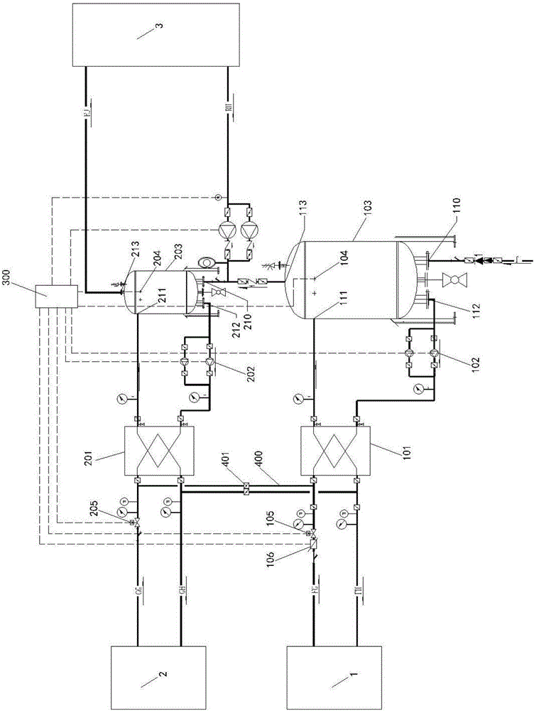
[0021] Waste heat supply phase:

[0022] Cold water enters the hot water storage tank 103 from the water supply port 110, and the temperature sensor 104 is used to judge the water temperature of the hot water storage tank 103. When the water temperature does not meet the preset condition 1, the solenoid valve 105 is opened, and the waste heat energy 1 passes through the heat exchanger. 101, start the internal circulation pump 102 between the hot water storage tank 103 and the heat exchanger, cold water enters the heat exchanger 101 from the inner circulation outlet 112 of the hot water storage tank, exchanges heat with the waste heat energy 1, and flows from the hot water storage tank The circulating water inlet 111 enters to heat the water in the hot water storage tank 103 . When the water temperature satisfies preset condition 1, the No....


PUM


Abstract

The invention relates to a closed type heat-exchange hot water system utilizing intermittently supplied waste heat. The closed type heat-exchange hot water system comprises a waste heat energy source system and a standby energy source system. A standby energy source serves a small hot water tank buffer tank, so that a water temperature of outlet water is quickly and flexibly regulated, initial cost and operation cost are saved, and use comfort of a user is improved.

Description

technical field [0001] The invention relates to the field of waste heat utilization hot water engineering, in particular to a closed heat exchange hot water system utilizing intermittent supply of waste heat. Background technique [0002] Distributed energy technology is a new energy technology that has developed rapidly in China in recent years, and its energy cascade utilization can greatly improve energy utilization. The technology generates a large amount of waste heat during operation to produce hot water. Because of its energy-saving, high-efficiency, green and environmental protection features, it has been more and more widely used in industrial parks, large office areas, hospitals, hotels and other places. [0003] Due to the application characteristics of distributed energy technology, its operating time period, that is, the waste heat generation time period is not completely consistent with the user's hot water use time period. Usually, a large amount of waste hea...

Claims


Application Information

Patent Timeline
Patent Type & Authority Applications(China)
IPC IPC(8): F24D17/00F24D19/10F24D19/00
CPCY02B30/18F24D17/0057F24D19/00F24D19/1051F24D2200/16F24D2220/08
Inventor 李亭颖田雪刚谭俊伟李婷吕清浩吴蔚兰
Owner CMCU ENG
Why Eureka
Try Eureka