
air conditioner

An air-conditioning device and installation slot technology, applied in air-conditioning systems, space heating and ventilation, space heating and ventilation details, etc., can solve problems such as complex assembly, cumbersome operation, and wall damage, so as to prevent movement and adjust Flexible, Stability-Enhancing Effects

Active Publication Date: 2020-02-04
GD MIDEA AIR-CONDITIONING EQUIP CO LTD
View PDF8 Cites 0 Cited by
  • Summary
  • Abstract
  • Description
  • Claims
  • Application Information

AI Technical Summary

Problems solved by technology

During the assembly process, it is necessary to set lines and pipeline through holes on the wall, which not only causes damage to the wall, but also cumbersome operation and complicated assembly

Method used


Image

  • air conditioner
  • air conditioner
  • air conditioner

Examples


Embodiment 1

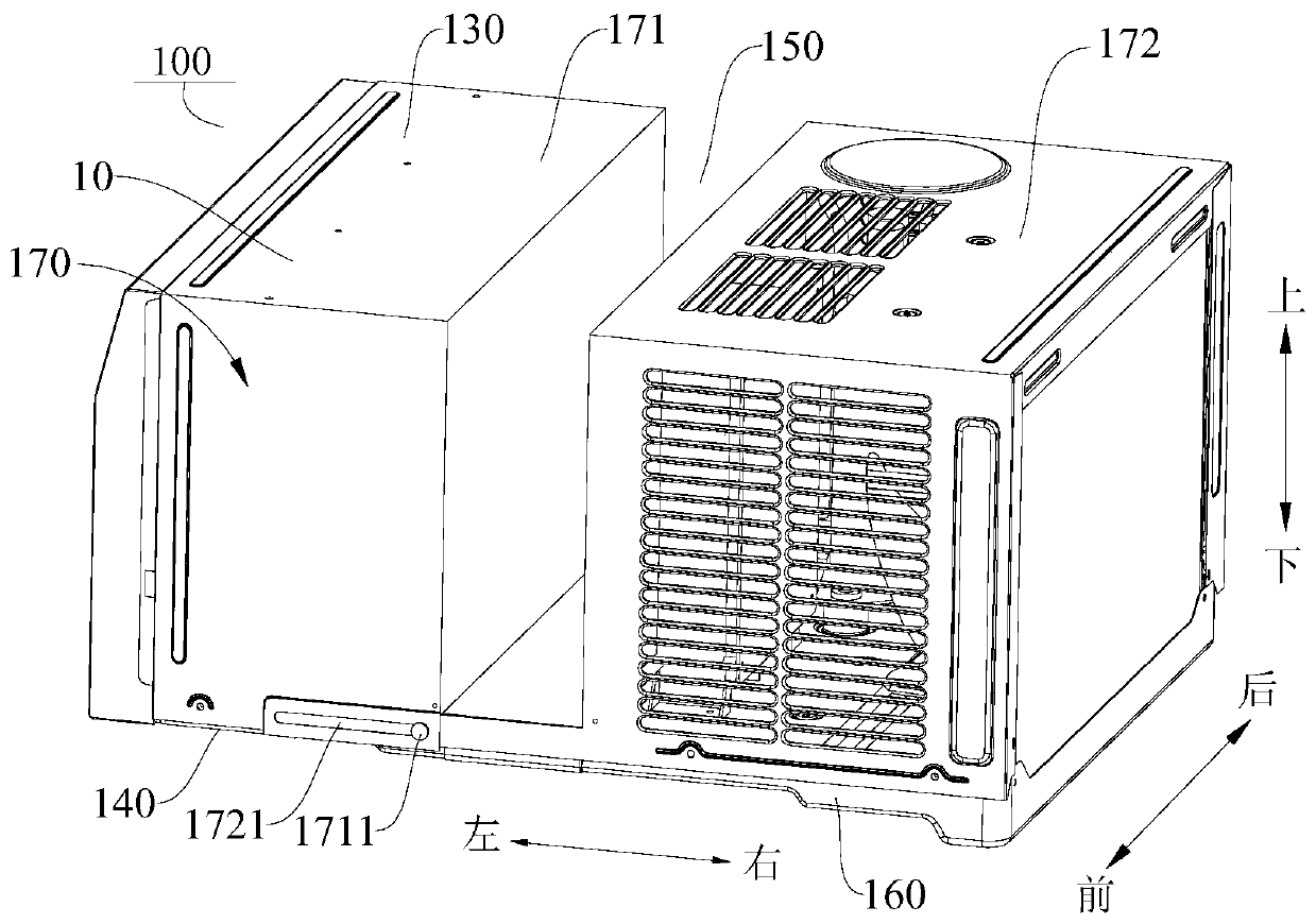
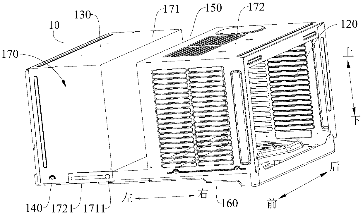
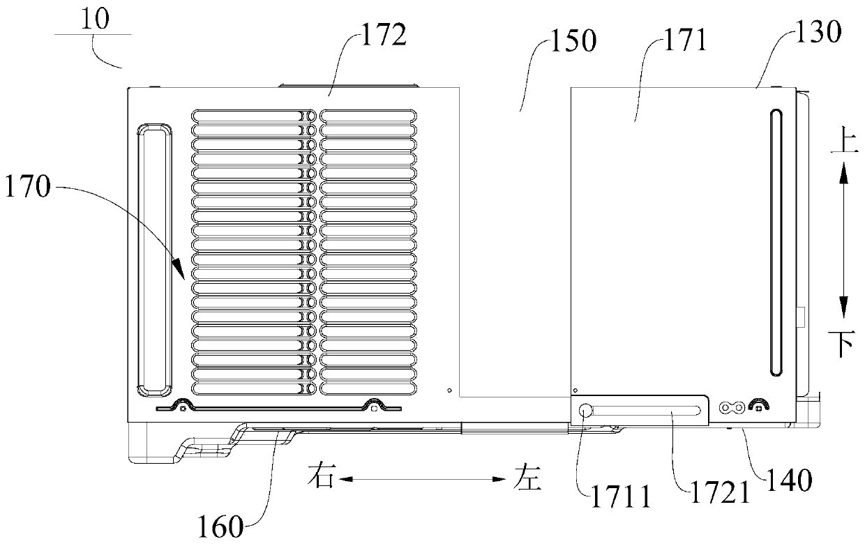
[0082] Such as Figure 1-Figure 11 As shown, the air conditioner 100 includes: a casing 10 , an indoor unit assembly 20 and an outdoor unit assembly 30 .

[0083] Among them, such as figure 2 , Figure 5 and Figure 6 As shown, the casing 10 is generally a cuboid structure, and the casing 10 includes an outer cover 170 and a chassis 160 , and the outer cover 170 is disposed on the chassis 160 . The enclosure 170 includes an indoor enclosure 171 and an outdoor enclosure 172 , and the chassis 160 includes an indoor chassis 161 and an outdoor chassis 162 . An indoor cavity 110 is defined between the indoor outer cover 171 and the indoor chassis 161 , and the indoor unit assembly 20 is disposed in the indoor cavity 110 . An outdoor cavity 120 is defined between the outdoor cover 172 and the outdoor chassis 162 , and the outdoor unit assembly 30 is disposed in the outdoor cavity 120 . A connecting plate 173 is arranged between the indoor outer cover 171 and the outdoor outer ...

Embodiment 2

[0091] Such as Figure 12 As shown, different from Embodiment 1, in this embodiment, the air conditioner 100 has two connecting plates 173, and the two connecting plates 173 are along the up and down direction (such as Figure 12 Up and down directions shown in ) stack settings. The lower connecting plate 173 is vertically connected to the indoor cover 171 , and the upper connecting plate 173 is vertically connected to the outdoor cover 172 . The two connecting plates 173 are slidable along the left and right directions, thus, the groove width of the installation groove 150 can be adjusted according to the specific thickness of the wall.

Embodiment 3

[0093] Such as Figure 13 As shown, different from the first embodiment, in this embodiment the air conditioner 100 has two connecting plates 173 . Wherein the connecting plate 173 on the left side can be rotated. When the connecting plate 173 is rotated to the horizontal direction, the connecting plate 173 can be pulled out from the indoor cavity 110 to increase the width of the bottom wall of the installation groove 150 of the air conditioner 100 . When the width of the bottom wall of the installation groove 150 is reduced, the connecting plate 173 can protrude into the interior chamber 110 and be rotatably attached to the right side wall of the interior and exterior cover 171 . Thus, the structure is simplified, and the groove width of the mounting groove 150 can be adjusted.


PUM


Abstract

The invention discloses an air conditioning device. The air conditioning device includes a housing, an indoor unit assembly, an outdoor unit assembly; an indoor cavity and an outdoor cavity are separately defined in the housing, and communicate with each other; the center of a top wall or a bottom wall of the housing recesses toward the inner cavity of the housing so as to form an installation groove outside the huosing; the installation groove is positioned between the indoor cavity and the outer cavity, and the width of the installation groove can be adjusted in the distribution direction of the indoor cavity and the outdoor cavity; and the indoor unit assembly is arranged in the indoor cavity, and the outdoor unit assembly is arranged in the outdoor cavity and is connected to the indoor unit assembly. According to the air conditioning device, the air conditioning device can be easily and efficiently clamped on a wall above a window frame through the installation groove positioned between the indoor cavity and the outdoor cavity, the indoor cavity communicates with the outdoor cavity, arrangement of connection pipes and lines is facilitated, and holes formed in the window and the wall can be avoided; and the width of the installation groove of the air conditioning device can be adjusted, shifting of the air conditioning device can be prevented, and the installation reliability of the air conditioning device can be enhanced.

Description

technical field [0001] The present invention relates to the technical field of air conditioning, and more specifically, to an air conditioning device. Background technique [0002] In the related art, the indoor unit and the outdoor unit of the air conditioner are installed separately, the indoor unit is installed indoors, and the outdoor unit is installed outdoors, and the indoor unit and the outdoor unit are connected by pipelines and lines. During the assembly process, it is necessary to arrange wiring and pipeline through holes on the wall, thereby not only causing damage to the wall, but also cumbersome operation and complicated assembly. Contents of the invention [0003] The present invention aims to solve one of the technical problems in the related art at least to a certain extent. Therefore, the present invention proposes an air conditioner, which has the advantages of simple structure and convenient assembly. [0004] The air conditioner according to the embod...

Claims


Application Information

Patent Timeline
Patent Type & Authority Patents(China)
IPC IPC(8): F24F1/027F24F13/20F24F1/0323F24F13/30
CPCF24F1/027F24F13/20F24F13/30F24F2013/202
Inventor 饶伟
Owner GD MIDEA AIR-CONDITIONING EQUIP CO LTD
Learn More