Humidifier

A humidifier and water tank technology, applied in air humidification systems, heating methods, lighting and heating equipment, etc., can solve the problems of high processing cost, high cost, high noise, etc., and achieve a simple structure, low cost, and simple device structure. Effect

Active Publication Date: 2017-05-31
GREE ELECTRIC APPLIANCES INC
View PDF5 Cites 3 Cited by
  • Summary
  • Abstract
  • Description
  • Claims
  • Application Information

AI Technical Summary

Problems solved by technology

However, the inventors of the present invention have found that the electromagnetic valve control device has a complicated structure and high cost; the water pump pumping device not only has a complicated structure and high processing cost, but also has relatively high noise.

Method used


Image

  • Humidifier
  • Humidifier
  • Humidifier

Examples


Embodiment 1

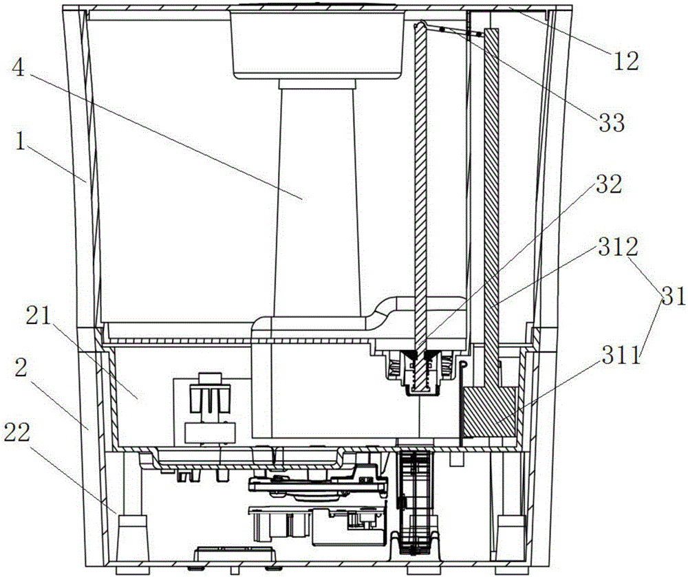
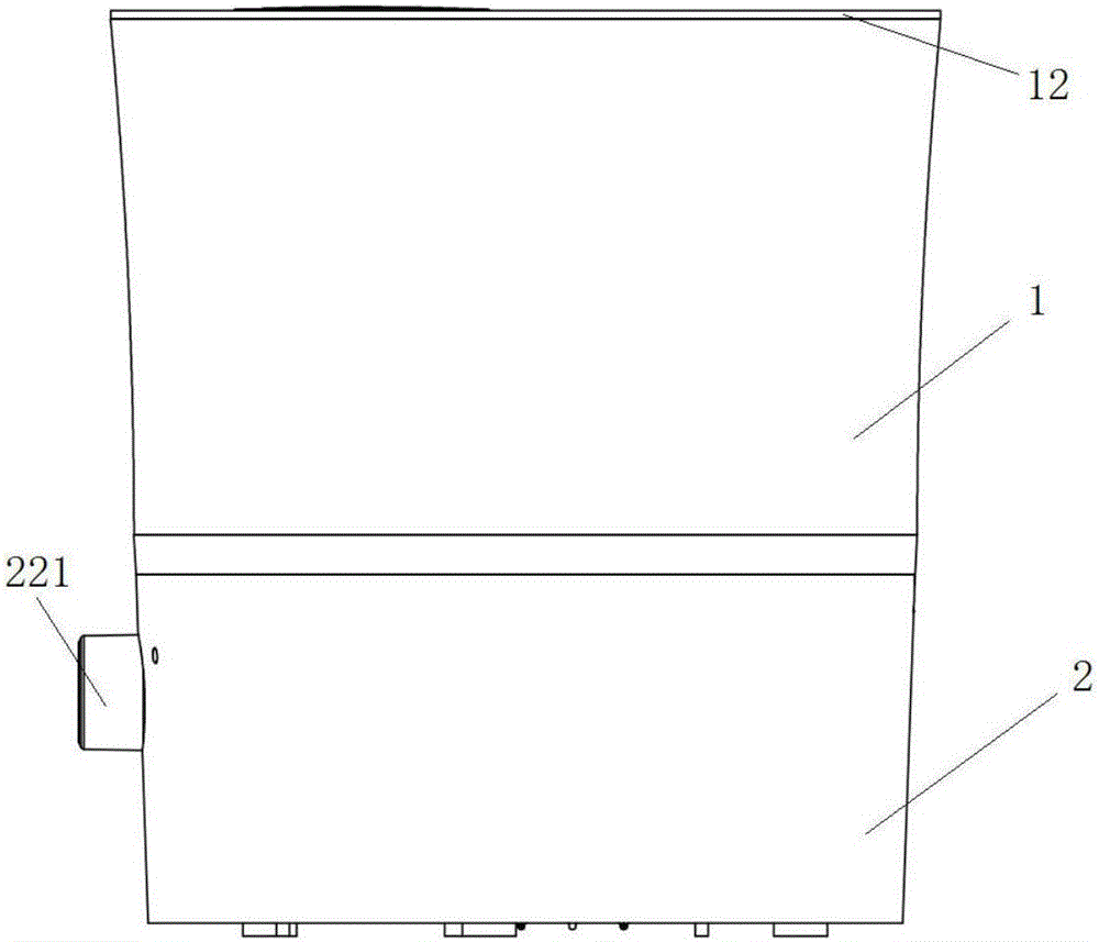
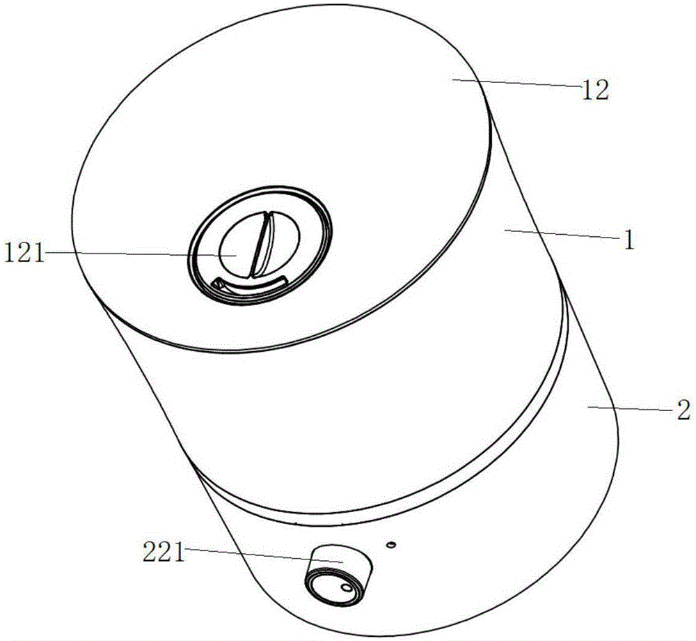
[0086] This embodiment provides a humidifier, wherein the humidifier is an upper water humidifier, specifically, as Figure 1 to Figure 6 , Figure 28 As shown, the humidifier of this embodiment includes a water tank assembly 2, a water tank 1 and a water level control device. Wherein, the sink assembly 2 includes a base 22 and a sink 21 disposed on the base 22 . The water tank 1 is installed on the water tank 21; wherein, the upper end of the water tank 1 is provided with a water inlet for filling water into the water tank, and the bottom of the water tank 1 is provided with a water outlet 11 for allowing the water in the water tank 1 to enter the water tank 21. The water level control device includes a water level control switch 32 , a float device 31 and a transmission mechanism 33 . Wherein, the water level control switch 32 is used to control the opening or closing of the water outlet 11 . The float device 31 floats up and down as the water level in the water tank 21 c...

Embodiment 2

[0090] Preferably, this embodiment provides a humidifier, compared with the previous embodiment, such as figure 1 and Figure 28 As shown, the water level control switch 31 is arranged at the water outlet 11 of the water tank 1 . And, the water level control switch 31 can move up and down under the effect of force. Wherein, when the water level control switch 31 is in the first position, the water level control switch 31 closes the water outlet 11 .

[0091] Preferably, if Figure 16 to Figure 19 , Figure 28 As shown, the water level control switch mainly includes: a valve core 321 , a valve body 322 and a spring 323 . Wherein, the valve core 321 is connected with the transmission mechanism. The valve body 322 is sleeved on the valve core 321 , and the valve body 322 is used to block the drain port 11 . The spring 323 is sleeved on the valve core 321, and one end of the spring 323 is fixed to the valve core 321, and the other end is fixed to the water tank, and is used ...

Embodiment 3

[0095] Preferably, this embodiment provides a humidifier, compared with the above embodiments, such as Figure 12 to Figure 15 , Figures 20 to 23 As shown, the float device in this embodiment includes a float 311 and a connecting rod 312 . Wherein, the float 311 is arranged in the water tank 21, and the connecting rod 312 is connected to the upper end of the float 311, wherein the connecting rod 312 is connected with the transmission mechanism. Through such arrangement, the structure of the buoy device is simple and the cost is low.

[0096] Preferably, if Figure 14 and Figure 15 As shown, a limiting structure for assembling and positioning the float 311 is also provided in the water tank. Wherein, the limit structure makes the float device only float up and down, and limits the highest position of the float 311 in the water tank 21 . Preferably, the limiting structure includes a plurality of buckles 211 arranged around the float 311; wherein, the lower end of the buck...


PUM


Abstract

The invention relates to the technical field of household appliances, in particular to a humidifier. According to the main technical scheme, the humidifier comprises a water channel assembly, a water tank and a water level control device. The water channel assembly comprises a base and a water channel formed in the base. The water tank is installed on the water channel. The upper end of the water tank is provided with a water inlet used for injecting water into the water tank, and the bottom of the water tank is provided with a drain opening used for making the water in the water tank enter the water channel. The water level control device comprises a water level control switch, a floater device and a transmission mechanism. The transmission mechanism is used for connecting the water level control switch and the floater device. When the water level in the water channel is lower than a set working water level, the water level control switch can open the drain opening under the action of the floater device and the transmission mechanism. When the water level in the water channel is higher than the set working water level, the water level control switch can close the drain opening under the action of the floater device and the transmission mechanism. The humidifier is capable of achieving the upper water adding function, simple in structure and low in cost.

Description

technical field [0001] The present invention relates to the technical field of household appliances, in particular to a top water humidifier. Background technique [0002] With the improvement of living conditions, people have higher and higher requirements for the comfort of living environment. Among them, the humidity of the air is one of the important factors affecting comfort, especially in dry areas. Therefore, humidifiers are increasingly becoming an essential small household appliance for many families. [0003] At present, most humidifiers on the market are lower water humidifiers. The water inlet and water outlet of the lower water humidifier are located at the bottom of the water tank. When adding water to the lower water humidifier, the user needs to lift the water tank first, then turn the water tank over so that the bottom of the water tank faces upwards, then open the water tank nut, add water through the water inlet, and then tighten the water tank nut afte...

Claims


Application Information

Patent Timeline
Patent Type & Authority Applications(China)
IPC IPC(8): F24F6/00F24F11/00
CPCF24F6/00F24F11/0008F24F2006/008Y02B30/70
Inventor 林志荣王红兵侯剑飞林振华
Owner GREE ELECTRIC APPLIANCES INC
Why Eureka
Try Eureka