

Spray tank type heat exchanger and using method thereof
A technology of heat exchangers and spray tanks, applied in evaporators/condensers, lighting and heating equipment, refrigeration components, etc., can solve problems such as difficult operation, complicated connection structure, and unsatisfactory heat exchange efficiency, and improve efficiency , Improve the effect of performance
Pending Publication Date: 2017-05-31
罗众锋 +1
View PDF7 Cites 0 Cited by
- Summary
- Abstract
- Description
- Claims
- Application Information
AI Technical Summary
Problems solved by technology
Heat pump units usually use spray tank heat exchangers as condensers. Due to structural limitations, existing spray tank heat exchangers can only be used as condensers to exchange heat from gaseous refrigerants into liquid refrigerants. , and cannot be used as an evaporator. If you want to cool the cooling medium, you need to connect the evaporator and other corresponding auxiliary equipment. This structure makes the heat exchange cost of the heat pump unit high, the connection structure is complicated, it is not easy to operate, and the heat exchange efficiency not ideal
Method used
View moreImage
Smart ImageViewing Examples

Examples
Embodiment 2
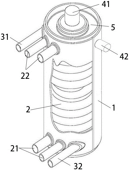
[0040] Embodiment 2, the gaseous refrigerant inlet 31 on the spray tank heat exchanger is omitted, and only the liquid refrigerant inlet 41 is reserved, and the liquid refrigerant inlet 41 is used for both gaseous refrigerant and liquid refrigerant. The refrigerant enters, and the gaseous refrigerant inlet 31 and the liquid refrigerant inlet 41 are combined into one, so that the structure of the heat exchanger is simpler and the operation is more convenient.
Login to View More PUM
 Abstract
The invention relates to the technical field of heat exchangers, in particular to a spray tank type heat exchanger and a using method thereof. The spray tank type heat exchanger comprises an outer barrel-shaped shell and a shaft core arranged inside the shell. A spiral coil pipe winding on the shaft core is arranged between the shell and the shaft core. A cooling medium flows in the spiral coil pipe. The cooling medium enters through a coil pipe inlet formed in the lower portion of the shell and flows out through a coil pipe outlet formed in the upper portion of the shell. A refrigerant flows through the space between the interior of the shell and the exterior of the spiral coil pipe, and the refrigerant enters and flows out through a condenser inlet / outlet structure or enters and flows out through an evaporator inlet / outlet structure. The spray tank type heat exchanger can be applied as a condenser as well as an evaporator, an independent evaporator is omitted, thus, a connection circuit structure is simpler, the heat exchange cost is reduced, and the heat exchange efficiency is improved.
Description
technical field [0001] The invention relates to the technical field of heat exchangers, in particular to a spray tank heat exchanger and a method for using the same. Background technique [0002] As the country implements environmental protection and energy saving policies to realize a conservation-oriented society, high-efficiency and energy-saving water source / ground source heat pump units have been developed rapidly. Heat pump units need to switch between cooling and heating modes. The system pipeline includes compressors, condensers, Throttling components, evaporators and other components. Heat pump units usually use spray tank heat exchangers as condensers. Due to structural limitations, existing spray tank heat exchangers can only be used as condensers to exchange heat from gaseous refrigerants into liquid refrigerants. , and cannot be used as an evaporator. If you want to cool the cooling medium, you need to connect the evaporator and other corresponding auxiliary eq...
Claims
Login to View More Application Information
Patent Timeline
 IPC IPC(8): F25B39/02F25B39/04
CPCF25B39/028F25B39/04F25B2339/0242F25B2339/046
Inventor罗众锋年介斌
Owner罗众锋