

A high-temperature pellet sensible heat recovery device and recovery method
A sensible heat recovery and high temperature technology, applied in steam generation methods using heat carriers, furnace control devices, waste heat treatment, etc.
- Summary
- Abstract
- Description
- Claims
- Application Information
AI Technical Summary
Problems solved by technology
Method used
Image

Examples
Embodiment Construction
[0045] In order to have a clearer understanding of the technical features, purposes and effects of the invention, the specific implementation manners of the present invention will now be described with reference to the accompanying drawings, in which the same reference numerals represent the same parts.
[0046] In this article, "schematic" means "serving as an example, example or illustration", and any illustration or implementation described as "schematic" should not be interpreted as a more preferred or more advantageous Technical solutions.
[0047] In order to make the drawings concise, the figures in each figure only schematically show the relevant parts of the present invention, and do not represent the actual structure of the product. In addition, to make the drawings concise and easy to understand, in some drawings, only one of the components having the same structure or function is schematically shown, or only one of them is marked.
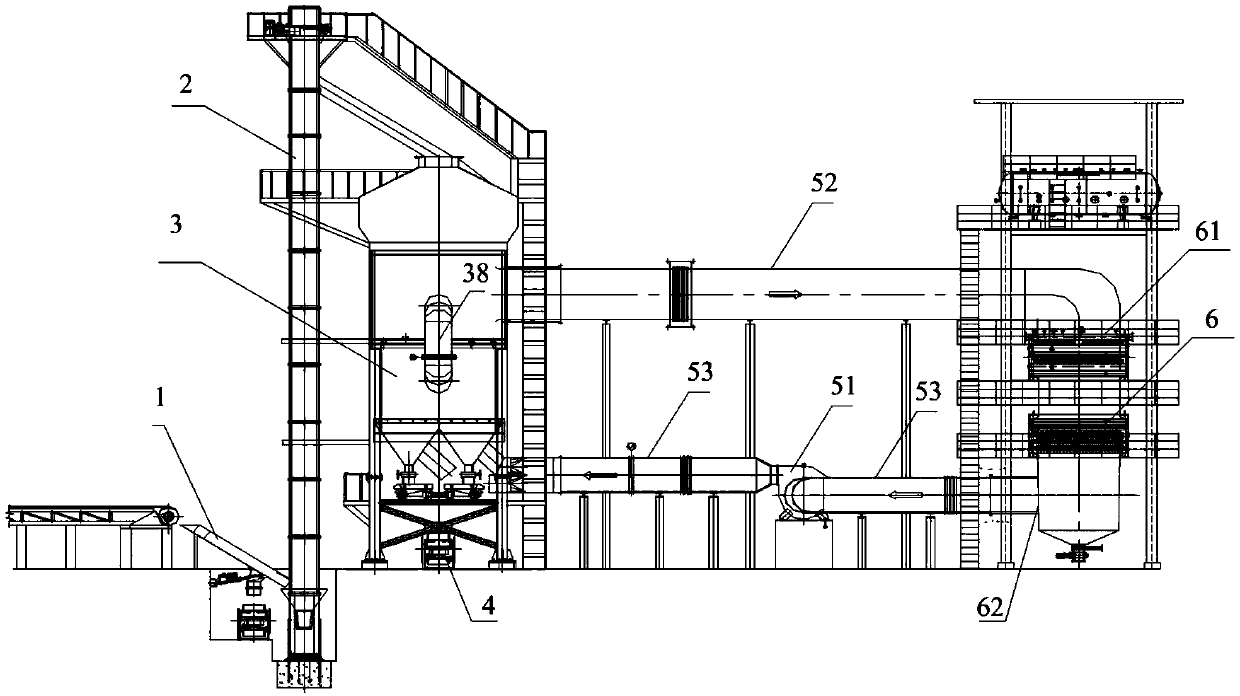
[0048] Such as figure 1 As sho...
PUM
 Abstract
Description
Claims
Application Information