Visible longitudinal-flow all-pin-fin tube lubricating oil cooler

A cooler and lubricating oil technology, which is applied to fixed tubular conduit components, heat exchanger types, heat exchanger shells, etc., can solve the problems of lubricating oil viscosity reduction, low heat exchange efficiency, and bulky equipment, and achieve Reduce flow resistance and improve heat transfer efficiency, flexible space layout

Active Publication Date: 2017-05-31
HEILONGJIANG UNIVERSITY OF SCIENCE AND TECHNOLOGY
View PDF5 Cites 2 Cited by
  • Summary
  • Abstract
  • Description
  • Claims
  • Application Information

AI Technical Summary

Problems solved by technology

As the temperature rises, the viscosity of the lubricating oil decreases. At this time, the lubricating oil cannot meet the lubrication and cooling requirements well.
If the lubricating oil in this case is directly lubricated to the friction parts without cooling, the mild ones will threaten the safe and stable operation of the equipment, and the severe ones will trigger the action of the safety protection system, or even damage the friction parts (such as bearings), resulting in operational accidents
[0004] At present, marine lubricating oil coolers generally use bare tube or plate coolers. The bare tube cooler has the disadvantages of low heat transfer efficiency, complex structure, and bulky equipment. Large resistance resistance, complex structure, high power requirements

Method used


Image

  • Visible longitudinal-flow all-pin-fin tube lubricating oil cooler
  • Visible longitudinal-flow all-pin-fin tube lubricating oil cooler
  • Visible longitudinal-flow all-pin-fin tube lubricating oil cooler

Examples


Embodiment Construction

[0021] The technical solution of the present invention will be further described below in conjunction with the accompanying drawings, but it is not limited thereto. Any modification or equivalent replacement of the technical solution of the present invention without departing from the spirit and scope of the technical solution of the present invention should be covered by the present invention. within the scope of protection.

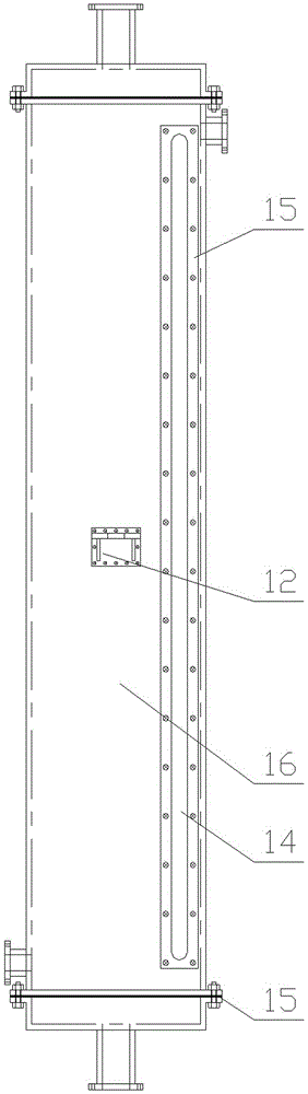
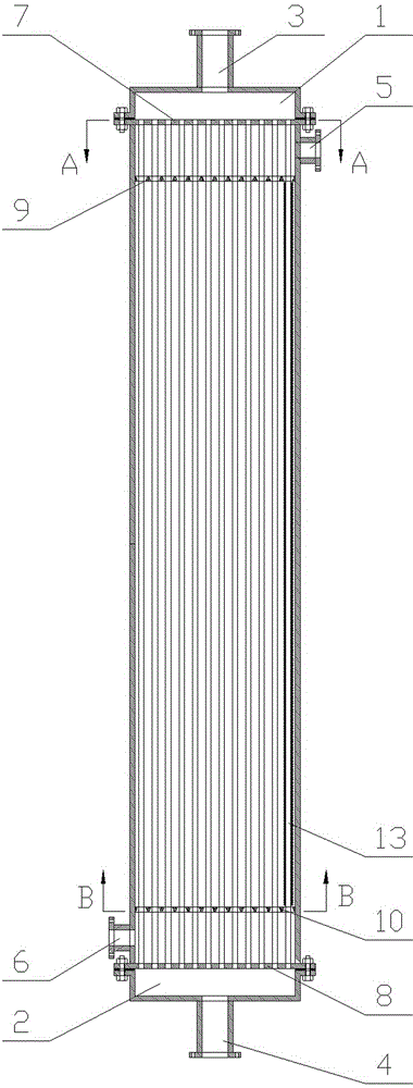
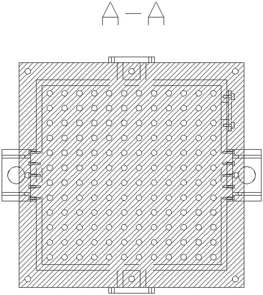
[0022] like figure 1 As shown, the longitudinal flow full pin-fin tube visible oil cooler of the present invention includes an integral pin-fin tube bundle 13, an upper oil spoiler 9, a lower oil spoiler 10, an upper tube plate 7, and a lower tube plate 8 , upper head 1, lower head 2, shell 16, wherein:

[0023] The upper tube plate 7 and the lower tube plate 8 are respectively fixed on the upper and lower end surfaces of the shell 16, the upper tube plate 7 is fixed with the upper head 1, and the lower tube plate 8 is fixed with the lower head 2, wher...


PUM


Abstract

The invention discloses a visible longitudinal-flow all-pin-fin tube lubricating oil cooler. The cooler comprises an integrated pin-fin tube bundle, an upper lubricating oil spoiler, a lower lubricating oil spoiler, an upper tube plate, a lower tube plate, an upper head, a lower head, and a shell. The upper tube plate and the lower tube plate are fixed to both upper and lower end faces of the shell, respectively. The upper head is fixed to the outside of the upper tube plate, while the lower head is fixed to the outside of the lower tube plate. The integrated pin-fin tube bundle is mounted in a plurality of rows between the upper tube plate and the lower tube plate. The upper lubricating oil spoiler and the lower lubricating oil spoiler are arranged on the integrated pin-fin tube bundle. A shell pass inlet and a shell pass outlet are formed in the shell, and a tube pass inlet and a tube pass outlet are formed in the upper head and the lower head. An interior oil fouling viewing slot is formed in the shell on the side of the shell pass inlet at the second row of pin-fin tubes, which is covered with a transparent organic glass plate. The cooler is simple in structure, simple to manufacture and mount, and convenient to use and maintain; With the use of the longitudinal flow mode, the flow resistance and the vibration of the tube bundle may be reduced, thereby allowing for prolonging of service life and saving of energy.

Description

technical field [0001] The invention relates to a lubricating oil cooler. Background technique [0002] Lubricating oil cooler is an important equipment commonly used in power plants, ships and other fields, and is widely used in power, nuclear energy, chemical, refrigeration, machinery and other industrial fields. Its task is to cool the lubricating oil to an appropriate temperature to ensure that the friction parts of the main and auxiliary equipment can be lubricated and cooled normally without causing accidents due to excessive lubricating oil temperature. [0003] After the lubricating oil passes through these friction parts, the oil temperature will generally rise by 20-30°C, or even higher. As the temperature rises, the viscosity of the lubricating oil decreases. At this time, the lubricating oil cannot meet the lubrication and cooling requirements well. If the lubricating oil in this case is directly lubricated to the friction parts without cooling, the mild ones w...

Claims


Application Information

Patent Timeline
Patent Type & Authority Applications(China)
IPC IPC(8): F28D7/16F28F9/24
CPCF28D7/16F28F9/24
Inventor 牛广林宋志勇尹冬松张翔阎昌琪南景富赵春香
Owner HEILONGJIANG UNIVERSITY OF SCIENCE AND TECHNOLOGY
Why Eureka
Try Eureka