

Switch hall sensor chopped wave delay measuring method and system
A Hall sensor and measurement method technology, applied in the field of sensors, can solve the problems of slowly changing magnetic field strength, difficult to directly test and obtain, single switching Hall sensor test method, etc., and achieves low cost of hardware equipment, difficult to directly measure and measure Simple steps to effect
- Summary
- Abstract
- Description
- Claims
- Application Information
AI Technical Summary
Problems solved by technology
Method used
Image

Examples
Embodiment 1
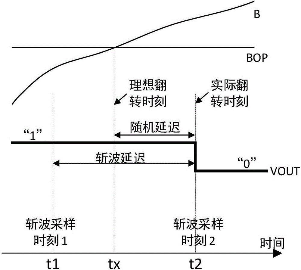
[0039] see figure 1 , the present invention discloses a method and system for measuring chopping delay of a switch-type Hall sensor. By placing a switch-type Hall sensor in a periodically changing magnetic field and observing the afterglow of the output signal of the sensor with an oscilloscope, the chopping delay can be indirectly measured. wave delay. Persistence display is a general display function of the oscilloscope, which can keep the waveform light spots on the oscilloscope display for a period of time.
[0040] test system such as Figure 4 As shown, it includes a device 100 capable of generating a periodically varying magnetic field, a DC power supply 200 , an oscilloscope 300 and a switch-type Hall sensor 400 to be tested. The switch-type Hall sensor includes at least 3 pins, which are power supply VCC, ground GND and output VOUT. Where VCC is connected to the positive output terminal of the DC power supply; GND is connected to the ground terminal of the DC power...
Embodiment 2
[0047] The difference between this embodiment and Embodiment 1 is that in this embodiment, step 1 is the same as step 2 and the first embodiment, and step 3 can be replaced with a falling edge trigger to observe the afterglow of the next rising edge, namely:
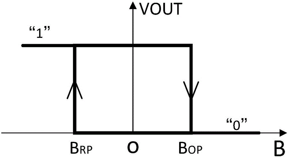
[0048] Step 3: Set the oscilloscope to trigger mode, use Figure 5 The falling edge of the middle square wave is used as the trigger edge, and at the same time turn on the afterglow display function of the oscilloscope. waveform like Figure 7 shown. Among them, BX is the ambient magnetic field strength, which decreases monotonically in this experiment; BRP is the threshold value of the magnetic release point, which is a constant value; BX is greater than BRP at the initial time, and will be less than BOP at the final time; the sensor output waveform displayed on the oscilloscope is VOUT. In the VOUT waveform, R is the falling edge used for triggering. After a period of time, VOUT will have a rising edge. According to ...
PUM
 Abstract
Description
Claims
Application Information