Sky eye detecting system

A technology of detection system and sky eye, which is applied in the field of target detection and radar system, can solve problems such as the limitation of target space range, and achieve the effect of improving discontinuity and reducing requirements

Inactive Publication Date: 2017-05-31
耿文东 +2
View PDF0 Cites 0 Cited by
  • Summary
  • Abstract
  • Description
  • Claims
  • Application Information

AI Technical Summary

Problems solved by technology

[0003] Whether it is a beam-scanning radar or a beam-dwelling radar, the basic condition for target detection is that the target must be within the radar beam in essence. Therefore, the above-mentioned problem existing in existing radars is that the spatial range of the target irradiated by the radar beam is limit

Method used


Image

  • Sky eye detecting system
  • Sky eye detecting system
  • Sky eye detecting system

Examples


Embodiment Construction

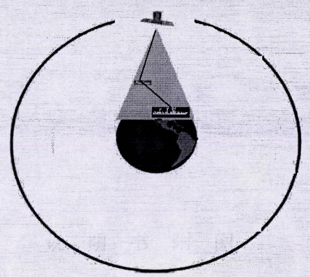
[0050] Taking geosynchronous orbit, that is, satellite in geostationary orbit as the launch system platform as an example, the present invention will be further described.

[0051] 1) Launch subsystem design

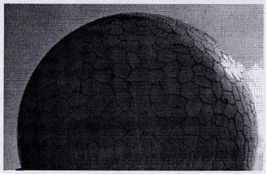
[0052] Using 3 geostationary orbit satellite platforms, deployed at 95°, 115° and 135° east longitude, the nominal altitude of the geostationary orbit is 35,786 kilometers, and the corresponding coverage area is 3,122 kilometers. If the center of the transmitting antenna is the equator, it will be formed centered on the equator An electronic inverted fence strip 3122 kilometers wide. Such as Figure 5 shown.

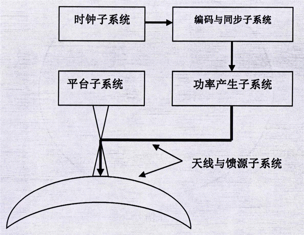
[0053] The transmission signal is designed as an X-band spread spectrum system, and the code length period is 1 millisecond. When the frequency is 10 GHz, the corresponding wavelength is 3 cm, the corresponding antenna half-power point beam width is 5°, and the corresponding antenna gain is 31.2 dB. The transmit power is 1500 watts, corresponding to 31.8dB w . ...


PUM


Abstract

The invention discloses a sky eye detecting system. The content of the sky eye detecting system includes the steps of S1, the mechanism and conception of the sky eye detecting system, S2, functions, S3, system composition, S4, a deployment rule and a scheme and S5, a direct wave restraining method. According to the system, an emitting system is carried on a medium orbit or high orbit or a bit elliptical orbit platform, and because the platform is high, emitting wave beams cover regions of interest without scanning all the time in a wide-area and seamless mode; a spherical surface antenna is carried on a ground or seaborne or aerial or near space or low-orbit space platform, and detected regions are covered without scanning in an all-around and seamless mode due to omni-directionality. The sky eye detecting system is applied to detection of ground, seaborne, aerial, near space, orbit and trajectory targets, has the advantages of being good in generality, high in survivability and maneuverability, diversified in function, large in detection region and wide in application range, and integrating target detection and state cognition, and achieves the situation that the targets continuously pass through the emitting wave beams and receiving wave beams; a user can obtain all-day plug-and-play target detection and state cognition service only by carrying a receiving system.

Description

technical field [0001] The invention belongs to the field of target detection, in particular to the field of radar systems. Background technique [0002] Radar is an important device for detecting ground, sea, air, near space and space targets. There are many classification methods of radar. According to the way the radar beam illuminates the target, it can be divided into three types: one is that the radar beam points to the target, and the radar beam moves with the movement of the target, such as air surveillance radar; the other is that the radar beam points to a certain area , the radar beam moves with the movement of the platform, such as space-based radar; the third is that the radar beam points to a certain direction, and the radar beam does not move while waiting for the target to pass through, such as an electronic fence. Of course, it also includes the combination of the above two or more methods, but in the final analysis, there are two types: beam-scanning radar...

Claims


Application Information

Patent Timeline
Patent Type & Authority Applications(China)
IPC IPC(8): G01S5/16
CPCG01S5/16
Inventor 耿文东耿歌杨丽
Owner 耿文东
Why Eureka
Try Eureka