
Optical fiber core butting matrix structure

A technology of docking matrix and optical fiber core, applied in the field of optical fiber core docking matrix structure, which can solve the problems of huge workload and time-consuming

Active Publication Date: 2017-05-31
NINGBO POWER SUPPLY COMPANY STATE GRID ZHEJIANG ELECTRIC POWER
View PDF4 Cites 1 Cited by
  • Summary
  • Abstract
  • Description
  • Claims
  • Application Information

AI Technical Summary

Problems solved by technology

[0003] At present, as the basic bearer network for optical fiber communication transmission - optical fiber network, its operation and maintenance work is still in the original manual mode, that is, it usually needs to manually go to the site to perform fiber jumping operations to realize the docking and exchange between different optical fibers, but it is limited by Influenced by many factors such as geographical dispersion and cumbersome manual switching operations, such manual operations are huge and time-consuming in daily work. Therefore, how to realize simple and efficient fiber core docking and switching has become a matter of great concern to people.

Method used


Image

  • Optical fiber core butting matrix structure
  • Optical fiber core butting matrix structure
  • Optical fiber core butting matrix structure

Examples


Embodiment Construction

[0034] As mentioned in the background technology section, in the prior art, people usually go to the site to perform fiber jumping operations to realize the docking and switching between different optical fibers. This manual method is time-consuming and labor-intensive.

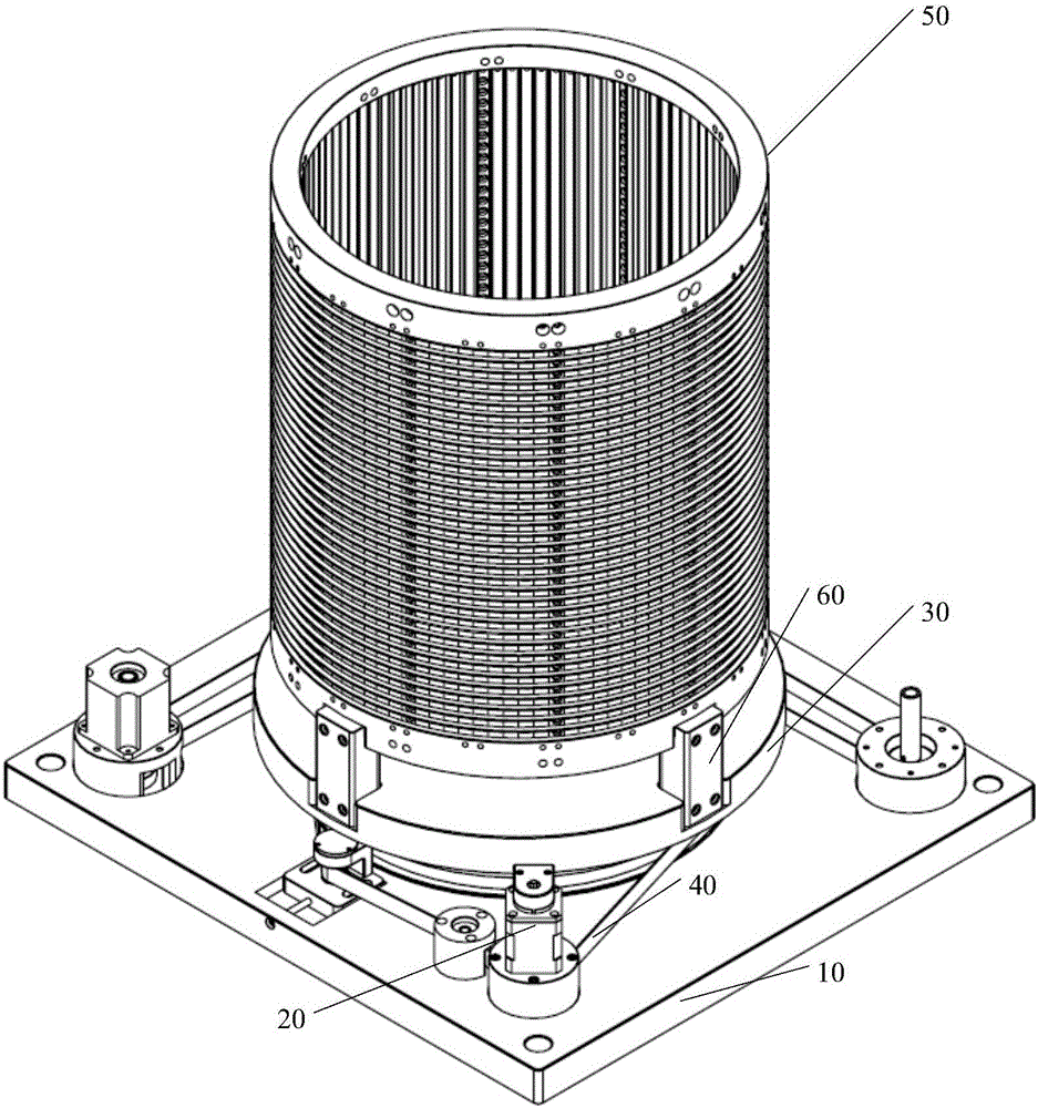
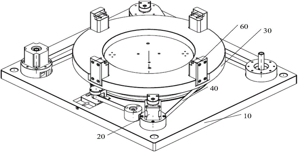
[0035] In view of this, an embodiment of the present invention provides an optical fiber core butt matrix structure, including:

[0036] base;

[0037] a first motor and a synchronous disc fixed on the base, the first motor drives the synchronous disc to rotate in a preset direction through a synchronous belt;

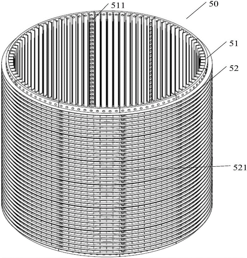
[0038] The docking matrix bucket fixedly connected with the synchronization plate, the docking matrix bucket is a hollow columnar structure, including a metal support structure and a plastic coating structure located on the outer surface of the support structure, wherein the side wall of the support structure has A plurality of butt holes arranged in a matrix along the first direction and the second...


PUM


Abstract

The embodiment of the invention discloses an optical fiber core butting matrix structure, which comprises a base, a first motor, a synchronization disk and a butting matrix barrel, wherein the first motor and the synchronization disk are fixedly arranged on the base, and the synchronization disk is driven by the first motor to rotate along a preset direction through a synchronous belt, and is fixedly connected with the butting matrix barrel. During specific work, the synchronization disk is driven by the first motor to rotate along the preset direction through the synchronous belt, and the butting matrix barrel is driven by the synchronization disk to synchronously rotate along the preset direction, so that the butting matrix barrel can perform rotation motion along the preset direction. Moreover, the butting matrix barrel comprises a metal support structure and a plastic wrapping structure positioned on the outer surface of the support structure, wherein the metal support structure is used for strengthening the strength of the butting matrix barrel and avoiding the top end of the butting matrix barrel inclining relative to the bottom end, and the plastic wrapping structure is used for correcting the shape of the metal support structure into a cylinder to facilitate subsequent optical fiber butting.

Description

technical field [0001] The invention relates to the technical field of optical fiber communication, in particular to an optical fiber core butt matrix structure. Background technique [0002] With the rapid development of power grid construction and the continuous improvement of power system equipment automation, the optical fiber power communication network has also achieved unprecedented development. [0003] At present, as the basic bearer network for optical fiber communication transmission - optical fiber network, its operation and maintenance work is still in the original manual mode, that is, it usually needs to manually go to the site to perform fiber jumping operations to realize the docking and exchange between different optical fibers, but it is limited by Influenced by many factors such as geographical dispersion and cumbersome manual switching operations, such manual operations are huge and time-consuming in daily work. Therefore, how to realize simple and effic...

Claims


Application Information

Patent Timeline
IPC IPC(8): G02B6/38
CPCG02B6/3891
Inventor 周开河俞红生吴笑章立伟俞佳捷孙晓恩李鹏范雪峰
Owner NINGBO POWER SUPPLY COMPANY STATE GRID ZHEJIANG ELECTRIC POWER
Learn More