MT stub
A ferrule and insertion hole technology, applied in the direction of light guides, optics, instruments, etc., can solve the problems of increased insertion loss, easy warping on both sides of the plane, insertion loss in the gap between ferrules, etc., to reduce insertion loss, reduce optical loss, Effect of Reducing Insertion Loss
- Summary
- Abstract
- Description
- Claims
- Application Information
AI Technical Summary
Problems solved by technology
Method used
Image

Examples
Embodiment 1
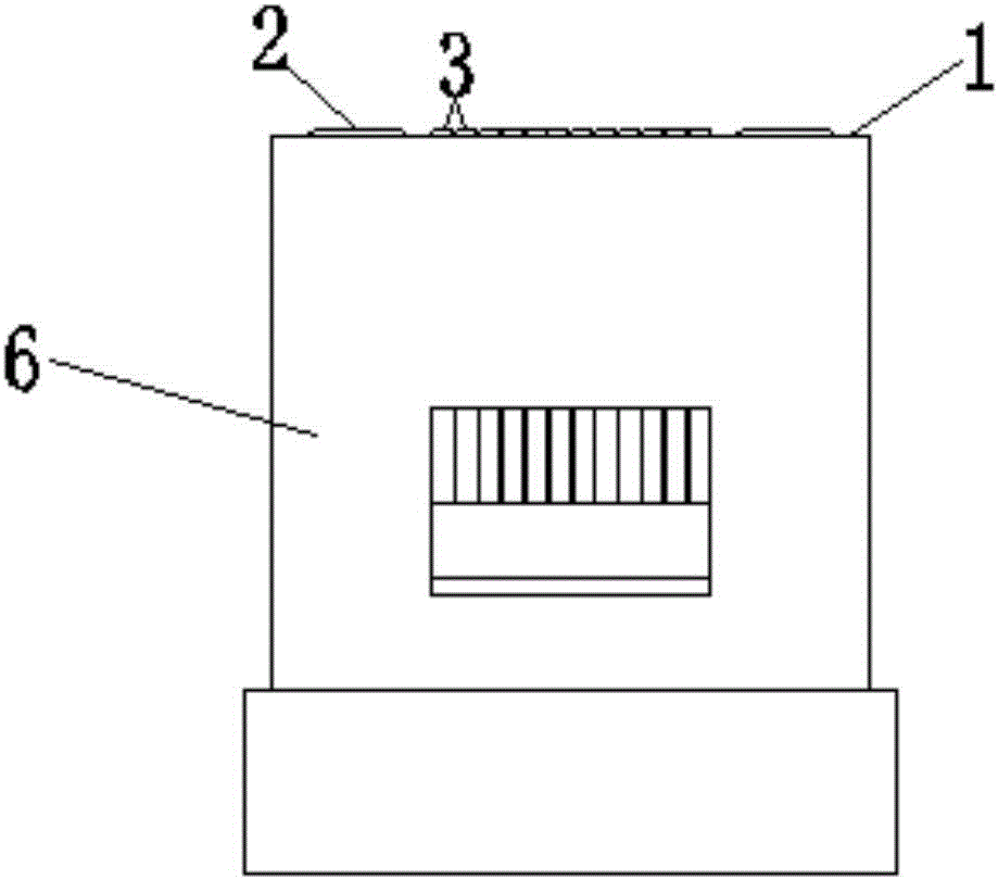
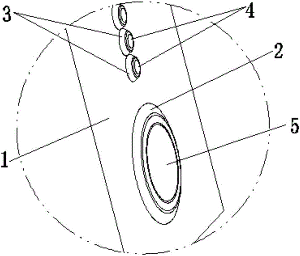
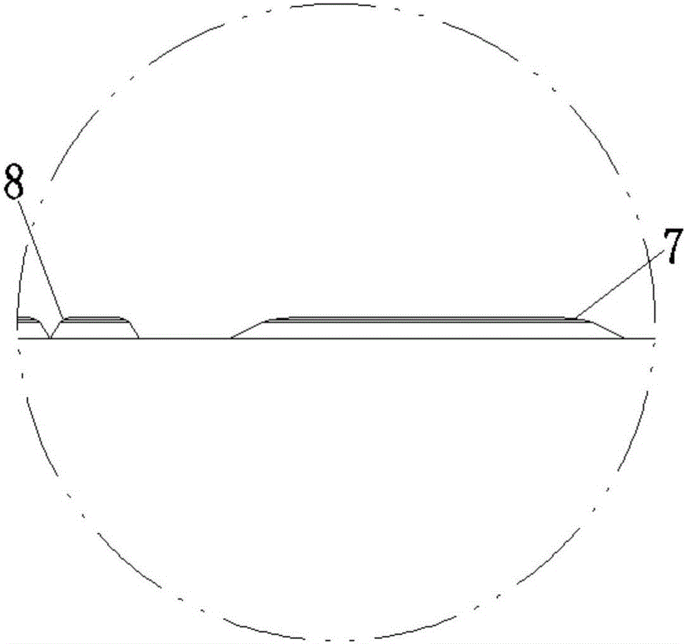
[0046] Such as figure 1 , figure 2 and image 3 As shown, a MT ferrule has a joint surface 1 at the front end of the ferrule 6, two first bosses 2 are arranged on the long axis direction of the joint surface 1, and the two first bosses 2 are arranged side by side. There are a number of second bosses 3, the first boss 2 and the second boss 3 include closely connected upper and lower parts, the upper surface 7 of the first boss upper part and the upper surface 8 of the second boss upper part are arcs On the surface, a guide hole 5 is provided in the middle of each first boss 2, and an optical fiber insertion hole 4 is provided in the middle of each second boss 3; the distance between the nearest two points of the two first bosses 2 is 3.2 mm, there is no gap between the adjacent sides of the second boss 3; in this embodiment, the lower parts of the first boss 2 and the second boss 3 are circular truncated, and the first boss 2 and the second boss The height of platform 3 re...
Embodiment 2
[0049] Such as Figure 4 , Figure 5 and Figure 6 As shown, a MT ferrule has a joint surface 1 at the front end of the ferrule 6, two first bosses 2 are arranged on the long axis direction of the joint surface 1, and the two first bosses 2 are arranged side by side. There are a number of second bosses 3, a guide hole 5 is provided in the middle of each first boss 2, and an optical fiber insertion hole 4 is arranged in the middle of each second boss 3; the two first bosses 2 are closest to the two The distance between the points is 3.2mm, and the distance between the nearest two points of the adjacent second boss 3 is 0.063mm; The height relative to the joint surface 1 is 0.005mm; the upper surface of the first boss 2 is circular, and the area of the bottom surface of the first boss 2 is 0.798mm 2 ; The upper surface of the second boss 3 is circular, and the area of the bottom surface of the second boss 3 is 0.027mm 2 ; A guide hole 5 is opened in the middle of each fi...
Embodiment 3
[0052] Such as Figure 7 , Figure 8 and Figure 9 As shown, a MT ferrule has a joint surface 1 at the front end of the ferrule 6, two first bosses 2 are arranged on the long axis direction of the joint surface 1, and the two first bosses 2 are arranged side by side. There are several second bosses 3, the first boss 2 and the second boss 3 both include upper and lower parts that are closely connected, and the upper surface of the first boss and the upper surface of the second boss are arc surfaces, A guide hole 5 is provided in the middle of each first boss 2, and an optical fiber insertion hole 4 is provided in the middle of each second boss 3; the distance between the closest two points of the two first bosses 2 is 3.2mm, The distance between the nearest two points of the adjacent second boss 3 is 0.122mm; in this embodiment, the lower part of the first boss 2 is a cylinder, the lower part of the second boss 3 is a cylinder, and the first boss 2 and the second The height ...
PUM
 Abstract
Description
Claims
Application Information
 - Generate Ideas
- Intellectual Property
- Life Sciences
- Materials
- Tech Scout
- Unparalleled Data Quality
- Higher Quality Content
- 60% Fewer Hallucinations
Browse by: Latest US Patents, China's latest patents, Technical Efficacy Thesaurus, Application Domain, Technology Topic, Popular Technical Reports.
© 2025 PatSnap. All rights reserved.Legal|Privacy policy|Modern Slavery Act Transparency Statement|Sitemap|About US| Contact US: help@patsnap.com