

Laser shaping system and device for detecting laser shaping system
A laser shaping and laser technology, applied in the field of lasers, can solve problems such as lack of parameter change detection function
- Summary
- Abstract
- Description
- Claims
- Application Information
AI Technical Summary
Problems solved by technology
Method used
Image

Examples
Embodiment 1
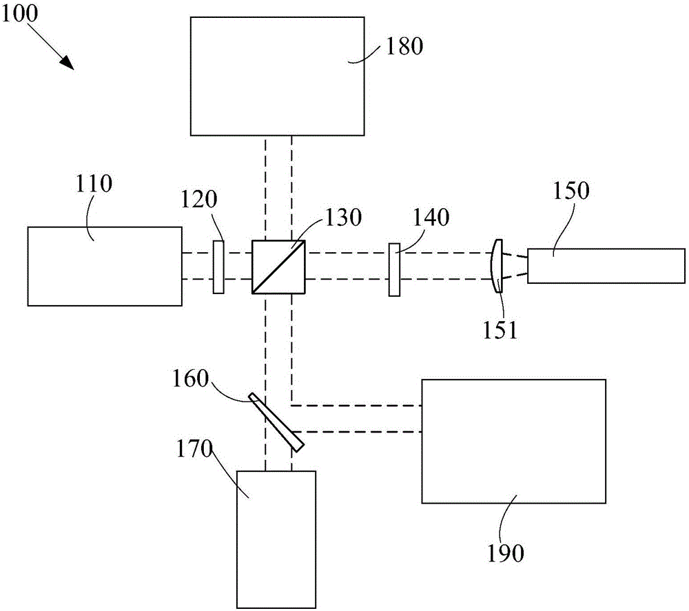
[0036] The invention provides a laser shaping system. see figure 1 , figure 1 It is a structural schematic diagram of an embodiment of the laser shaping system of the present invention. Such as figure 1 As shown, the laser shaping system 100 includes: a pre-stage laser 110, a 1 / 2 wave plate 120, a polarization beam splitter prism 130, a 1 / 4 wave plate 140, a stimulated Brillouin scattering phase conjugate mirror (SBS-PCM) 150, The lens 151 , the first spectroscopic element 160 , the subsequent laser 170 , the first detection component 180 and the second detection component 190 .
[0037] The pre-stage laser 110 is used to emit laser light to be shaped, and the 1 / 2 wave plate 120 is used to receive the laser light and change the polarization state of the laser light. The polarization beam splitter prism 130 is used to transmit most of the laser light output from the 1 / 2 wave plate to the first optical path, and the remaining part is reflected to the second optical path to o...
Embodiment 2
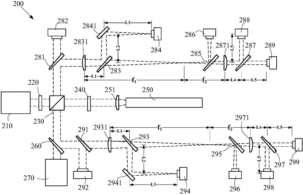
[0047] see figure 2 , figure 2 It is a structural schematic diagram of another embodiment of the laser shaping system of the present invention. Such as figure 2 As shown, the laser shaping system 200 includes: a pre-stage laser 210, a 1 / 2 wave plate 220, a polarization beam splitter prism 230, a 1 / 4 wave plate 240, an SBS-PCM250, a lens 251, a first light splitting element 260, and a post-stage laser 270 , the first detection component and the second detection component.
[0048] This embodiment and figure 1 Differences in the illustrated embodiments include:
[0049] (1) The first detection component includes a second spectroscopic element 281 and a first energy meter 282. The second spectroscopic element 281 is used to transmit part of the laser light emitted from the second optical path (that is, the laser light from the polarization beam splitter prism 230) to the second optical path. An energy meter 282, the remaining light is reflected to the fourth optical path ...
Embodiment 3
[0064] In an embodiment of the present invention, a detection device for a laser shaping system is also provided, including:
[0065] 1 / 2 wave plate, used to change the polarization state of the laser emitted by the front-end laser;
[0066] A polarization beam splitter is used to guide most of the laser light emitted by the 1 / 2 wave plate to the first optical path and the remaining part to the second optical path;
[0067] 1 / 4 wave plate, used to change the polarization state of the laser light emitted from the first optical path, and emit the laser light to the stimulated Brillouin scattering phase conjugate mirror SBS-PCM;
[0068] The first beam-splitting element, the laser reflected by the SBS-PCM back to the 1 / 4 wave plate is guided to the beam-splitting element through the polarization beam-splitting prism, and the beam-splitting element is used to guide most of the laser light to the subsequent laser, and the remaining part is guided to the third light path exit;
[...
PUM
 Abstract
Description
Claims
Application Information