
A Finite Element Mesh Size Determination Method for Concentrated Load Metal Joints

A technology of metal joints and grid size, applied in geometric CAD, design optimization/simulation, special data processing applications, etc., can solve problems such as low solution accuracy, high number of iterations, inaccurate division, etc., to improve solution accuracy and reduce The number of iterations, the effect of improving the accuracy of numerical solutions

Active Publication Date: 2020-04-10
XIAN AIRCRAFT DESIGN INST OF AVIATION IND OF CHINA
View PDF4 Cites 0 Cited by
  • Summary
  • Abstract
  • Description
  • Claims
  • Application Information

AI Technical Summary

Problems solved by technology

[0003] The purpose of the present invention is to provide a method for determining the finite element mesh size of the metal joint with concentrated load, which solves the problems of inaccurate division of the finite element grid of the metal joint with concentrated load, which leads to low solution accuracy and many iterations.

Method used


Image

  • A Finite Element Mesh Size Determination Method for Concentrated Load Metal Joints
  • A Finite Element Mesh Size Determination Method for Concentrated Load Metal Joints
  • A Finite Element Mesh Size Determination Method for Concentrated Load Metal Joints

Examples


Embodiment Construction

[0024] In order to make the objectives, technical solutions and advantages of the present invention clearer, the technical solutions in the embodiments of the present invention will be described in more detail below in conjunction with the drawings in the embodiments of the present invention. In the drawings, the same or similar reference numerals denote the same or similar elements or elements having the same or similar functions throughout. The described embodiments are some, but not all, embodiments of the invention. The embodiments described below by referring to the figures are exemplary and are intended to explain the present invention and should not be construed as limiting the present invention. Based on the embodiments of the present invention, all other embodiments obtained by persons of ordinary skill in the art without making creative efforts belong to the protection scope of the present invention. Embodiments of the present invention will be described in detail b...


PUM


Abstract

The invention relates to a method for determining the size of a finite element grid of a concentrated load-transfer type metal joint. The method is applicable to concentrated load-transfer type metal joints with complex geometric structures. The method comprises the following steps: (1) carrying out secondary unit grid division on the metal joint; (2) selecting a solver for solving; (3) checking a stress result, and determining a high-stress region of a structure; and (4) inquiring a unit integration point stress numerical value and a unit node numerical value of the high-stress region, if the two numerical values are the same, indicating that the size of the grid is reasonable, and if the two numerical values are quite different, further refining the grid and repeatedly carrying out the steps (2) to (4) until the two numerical values are the same. By virtue of the method for determining the size of the finite element grid of the concentrated load-transfer type metal joint, a structural numerical value solution can be accurately obtained, the finite element solution precision is improved, the defects caused by the depending of an ''experience'' method in the prior art are overcome, the number of iterations is decreased, and the solution precision of the numerical values is improved, so that the research cycle is shortened, and the research cost is lowered.

Description

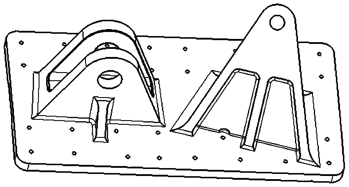
technical field [0001] The invention belongs to the technical field of aircraft structure strength analysis, and in particular relates to a method for determining the finite element grid size of a metal joint with concentrated load. Background technique [0002] Metal joints are widely used in modern aircraft. The function of metal joints is to connect the two parts of the main structure. Due to their complex geometry and large load level, the stress concentration of metal joint structures is serious. The metal joint structure is as follows: figure 1 As shown in the figure, the metal joint shown in the figure not only has a base part connected to other metal planes, but also has a joint part similar to other metal structures, and the base part and joint part are welded together. The mechanism mainly adopts the solid finite element analysis method, and the finite element analysis results are heavily dependent on the grid size. However, there is no written regulation on the de...

Claims


Application Information

Patent Timeline
Patent Type & Authority Patents(China)
IPC IPC(8): G06F30/23G06F30/15
CPCG06F30/15G06F30/23
Inventor 郑茂亮范瑞娟李健王立国
Owner XIAN AIRCRAFT DESIGN INST OF AVIATION IND OF CHINA
Learn More