Novel structure of inhibiting sway phenomenon in voltage stabilizer

A new type of structure and voltage stabilizer technology, applied in the direction of non-uniform reactors, thermal reactors, nuclear reactors, etc., can solve problems such as burnout, false triggering of safety signals, and water surface sloshing, so as to suppress sloshing, improve safety, and improve accuracy Effect

Active Publication Date: 2017-05-31
CHINA NUCLEAR POWER TECH RES INST CO LTD +2
View PDF5 Cites 7 Cited by
  • Summary
  • Abstract
  • Description
  • Claims
  • Application Information

AI Technical Summary

Problems solved by technology

At this time, the water surface in the pressurizer of the nuclear power plant will slosh non-linearly. In this case, the water in the pressurizer impacts the vessel wall of the pressurizer, causing different degrees of impact pressure on the inner wall of the pressurizer.
When the impact pressure is relatively large, the sloshing phenomenon may directly endanger the structural integrity of the voltage stabilizer
At the same time, the impact pressure caused by sloshing will have a more obvious impact on the water level measurement in the voltage stabilizer. When the sloshing phenomenon occurs in the voltage stabilizer, the measured water level is higher or lower than the actual water level. In this case, causing Frequent actions of the water level control system may even lead to false triggering of safety signals
In addition, when the sloshing phenomenon is severe, the top of the heating rod in the regulator may be exposed, causing the heating rod to fail to cool down in time and burn out
If the sloshing phenomenon in the voltage stabilizer cannot be effectively suppressed, the safety, reliability and economy of the nuclear power plant will be greatly reduced

Method used


Image

  • Novel structure of inhibiting sway phenomenon in voltage stabilizer
  • Novel structure of inhibiting sway phenomenon in voltage stabilizer
  • Novel structure of inhibiting sway phenomenon in voltage stabilizer

Examples


Embodiment Construction

[0024] The preferred embodiments of the present invention will be described below in conjunction with the accompanying drawings.

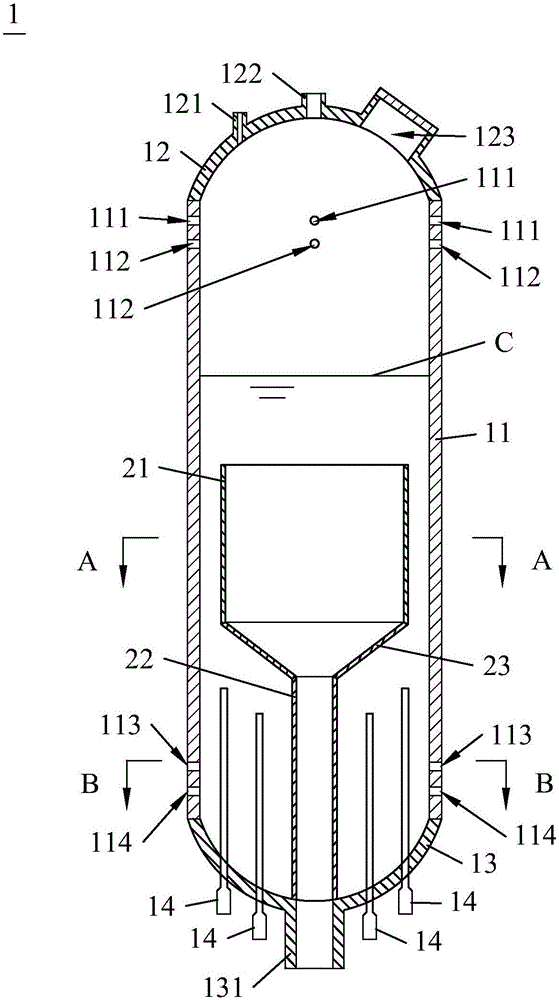
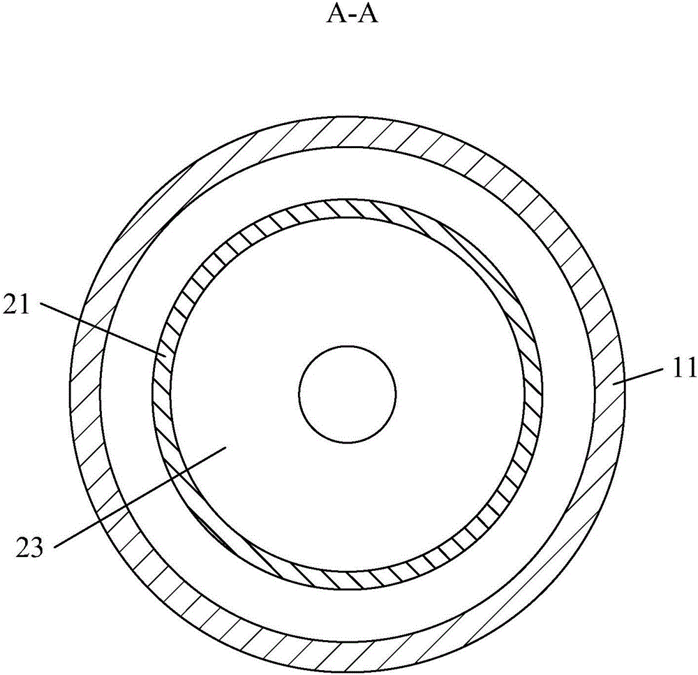
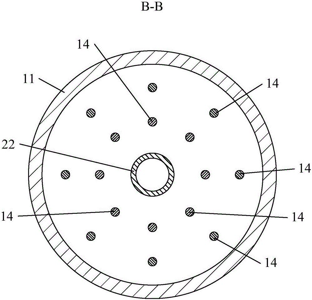
[0025] combine Figure 1 to Figure 3 As shown, the present invention provides a novel structure for suppressing the sloshing phenomenon in the voltage stabilizer, including the upper spacer 21 , the lower spacer 22 and the transition spacer 23 inside the voltage stabilizer 1 .

[0026] The voltage stabilizer 1 includes a cylindrical barrel body 11 , a hemispherical upper head 12 fixed on the upper end of the barrel body 11 , and a hemispherical lower head head 13 fixed on the lower end of the barrel body 11 . The upper head 12 is provided with a safety valve connecting pipe 121 communicating with the inside of the voltage stabilizer 1 , a spraying connecting pipe 122 and a manhole 123 for people to enter and exit. The inside of the upper head 12 is correspondingly provided with a spray head connected to the spray connection pipe 122. The spray con...


PUM


Abstract

The invention discloses a novel structure of inhibiting a sway phenomenon in a voltage stabilizer. The novel structure comprises an upper isolation piece and a lower isolation piece that are located in the voltage stabilizer, wherein the upper isolation piece and the lower isolation piece are in cylindrical structures extending in a height direction of the voltage stabilizer; the lower end of the lower isolation piece is fixed at the bottom of the voltage stabilizer; the upper isolation piece is fixed above the lower isolation piece and communicated with the lower isolation piece; the radial dimension of the upper isolation piece is greater than that of the lower isolation piece; and the upper end of the upper isolation piece is in an opening shape. An internal space of the voltage stabilizer is divided into an internal part and an external part by the upper isolation piece and the lower isolation piece, so that a diameter height ratio of the space is decreased; the sway phenomenon does not occur easily; at the same time, a fluid flow rate is limited radially; a vessel wall is protected; at the same time, heating rods at the bottom of the voltage stabilizer cannot be exposed; and in addition, the measurement accuracy of a water level in the voltage stabilizer is also ensured. Therefore, the novel structure facilitates improving safety, reliability and economy of a nuclear power plant.

Description

technical field [0001] The invention relates to the technical field of the main cooling system of a nuclear power plant, in particular to an internal structure of a voltage stabilizer. Background technique [0002] The voltage stabilizer is used in the primary circuit of the nuclear reactor and is an important component of the main cooling system of the nuclear power plant. When an accident occurs in the primary circuit and the pressure increases or decreases, the pressure of the primary circuit is automatically adjusted to ensure the normal operation of the primary circuit. [0003] The environment of sea-based nuclear power plants is harsher than that of land-based nuclear power plants. Under the influence of external conditions such as wind, waves, and ocean currents, the offshore floating platforms or ships carrying nuclear power plants will tilt, heave, and sway. At this time, the water surface in the pressurizer of the nuclear power plant will slosh non-linearly. In th...

Claims


Application Information

Patent Timeline
Patent Type & Authority Applications(China)
IPC IPC(8): G21C1/09G21C13/024
CPCG21C1/09G21C13/024Y02E30/30
Inventor 刘建昌杨江沈永刚罗汉炎纪文英卢向晖王婷
Owner CHINA NUCLEAR POWER TECH RES INST CO LTD
Why Eureka
Try Eureka