Eureka AIR delivers breakthrough ideas for toughest innovation challenges, trusted by R&D personnel around the world.

A full-band signal indoor digital TV receiving antenna

A digital TV receiving and signal room technology, applied in the direction of antenna, antenna support/installation device, electrical components, etc., can solve the problems affecting the layout of indoor objects and the space occupied by antenna, so as to achieve convenient location and strong receiving signal , the effect of low sound

Active Publication Date: 2019-05-14
ZHEJIANG LONGYOU XINXIDI ELECTRONICS
View PDF7 Cites 0 Cited by
  • Summary
  • Abstract
  • Description
  • Claims
  • Application Information

AI Technical Summary

Problems solved by technology

[0004] As can be seen from the above, some improvements have been made in the structure and function of the indoor TV antenna in the prior art, so that the antenna is more beautiful when placed indoors, but no matter how the antenna is placed indoors, it will always take up space, and in order to Improving the received signal strength also requires adjusting the posture of the antenna, which will affect the layout of indoor objects

Method used


Image

  • A full-band signal indoor digital TV receiving antenna
  • A full-band signal indoor digital TV receiving antenna
  • A full-band signal indoor digital TV receiving antenna

Examples


Embodiment Construction

[0022] The present invention will be further described in detail below in conjunction with the accompanying drawings and specific embodiments.

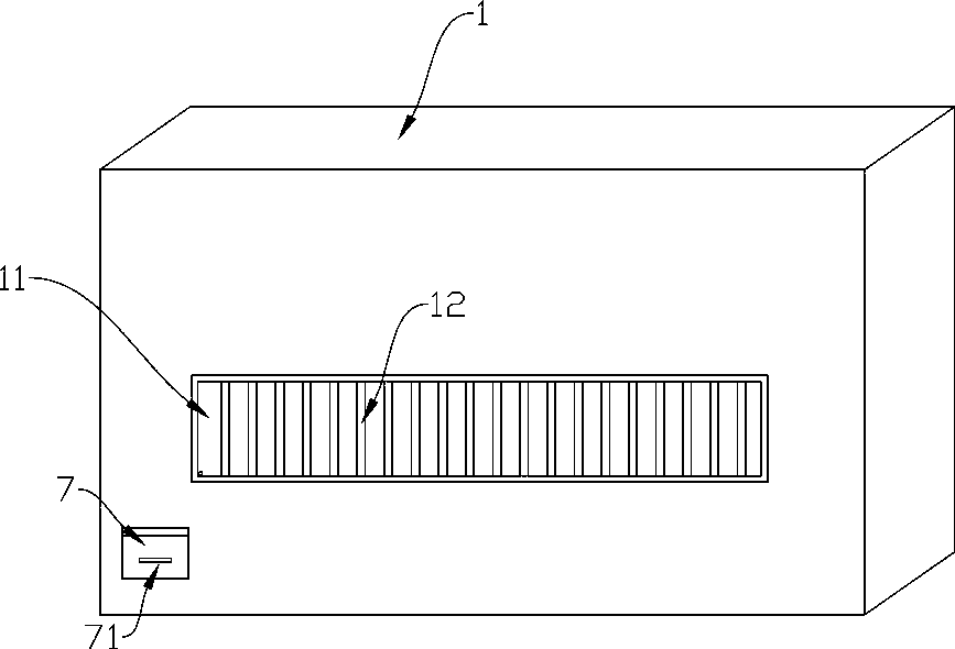
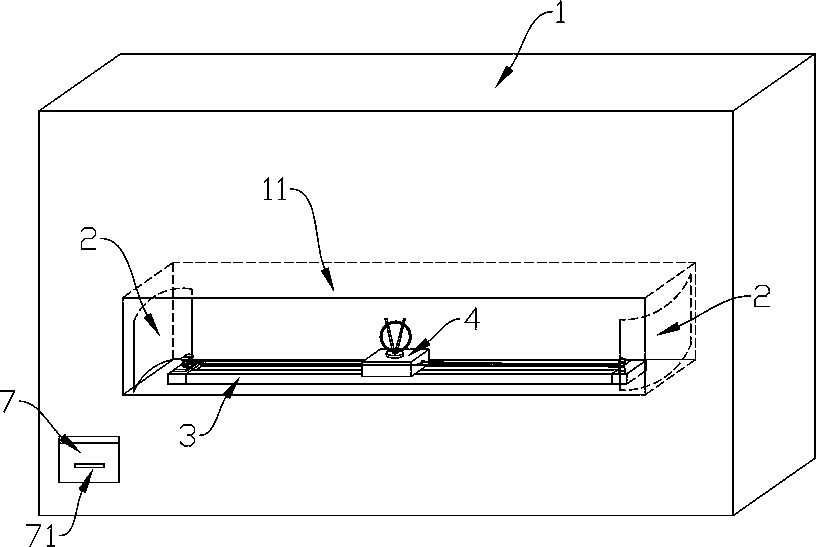
[0023] See Figure 1 to Figure 8 , a full-band signal indoor digital TV receiving antenna, including an installation cavity 11 located in the wall 1, a moving rail 3 located in the installation cavity 11, an antenna seat 4 located on the moving rail 3, and an The antenna 41 on the antenna base 4 is a full-band signal receiving antenna, and the antenna base is provided with antenna-related circuit components; wherein, the outer surface of the installation cavity 11 is provided with a hollow partition 12 to serve as a decoration function, the two sides of the installation cavity 11 are provided with metal sheets 2; the moving rail 3 is provided with a slideway 34 for the antenna seat 4 to move, and one end of the moving rail 3 is provided with two rotatable traction coils. Spool 31, the other end is provided with rotatable bobbin 32; O...


PUM


Abstract

Provided is a full-band signal indoor digital television receiving antenna, which comprises an installation cavity arranged in a wall body, a mobile rail arranged in the installation cavity, an antenna base arranged on the mobile rail and an antenna arranged on the antenna base. The outer surface of the installation cavity is provided with a hollow separator plate; the two sides of the installation cavity are respectively provided with a metal sheet; one end of the mobile rail is provided with two rotatable traction spools, and the other end thereof is provided with a rotatable line-passing reel. One of the traction spools is connected with one side of the antenna base through a traction line, and the other traction spool is connected with the other side of the antenna base through the traction line after the traction line passing around the line-passing reel. The antenna is arranged in the wall body, thereby preventing influence of the antenna on overall indoor decoration style; and meanwhile, the attitude and position of the antenna can be adjusted conveniently, and intensity of the received signal is high.

Description

technical field [0001] The invention belongs to the field of television antennas, and in particular relates to an indoor digital television receiving antenna for full-band signals. Background technique [0002] TV antennas are devices used by TVs to receive signals, and can be divided into outdoor antennas and indoor antennas. In areas with strong TV signals, indoor antennas can be used to receive signals, and in areas with weak TV signals, large outdoor antennas need to be installed. [0003] The indoor TV antennas in the prior art are generally independent receiving antennas, which affect the appearance of the TV indoors. For example, in the Chinese utility model patent with the announcement number CN201663227U, an indoor antenna for receiving TV VHF and UHF frequency bands is disclosed, which is mainly composed of a bottom box, an outer cover, a signal amplifier, a receiving sheet and a coil. It can be hung on the wall, or placed on a flat surface with a tripod, with a ...

Claims


Application Information

Patent Timeline
Patent Type & Authority Patents(China)
IPC IPC(8): H01Q3/08H01Q1/42H01Q1/12
CPCH01Q1/12H01Q1/42H01Q3/08
Inventor 童慧智童卿劳晓丽王涛胡柏华许红平
Owner ZHEJIANG LONGYOU XINXIDI ELECTRONICS
Why Eureka
Eureka Blog
Learn More