Wire laying method

A wire and wire collection technology, which is applied in the directions of cable laying equipment, transportation and packaging, thin material processing, etc., can solve the problems of messy construction site, interweaving wires, etc., to reduce labor intensity, increase adhesion, and improve wire collection efficiency Effect

Active Publication Date: 2022-01-21
CHINA FIRST METALLURGICAL GROUP
View PDF23 Cites 0 Cited by
  • Summary
  • Abstract
  • Description
  • Claims
  • Application Information

AI Technical Summary

Problems solved by technology

[0003] In order to solve the large workload of wiring and assembly in the prior art, it is often transported from the general power distribution room on the upper floor to the distribution room on the lower floor. After fatigue, the problem of low efficiency of wiring and transmission lines, as well as the problems of interweaving wires and messy construction sites, the present invention provides a method for laying and transmitting wires, which replaces most of the labor with machinery, thereby improving the collection efficiency of wiring and transmission lines. Line efficiency, and at the same time through various devices, wiring, transmission, and collection, so as to solve the problems of interweaving wires and messy construction sites

Method used


Image

  • Wire laying method
  • Wire laying method
  • Wire laying method

Examples


Embodiment 1

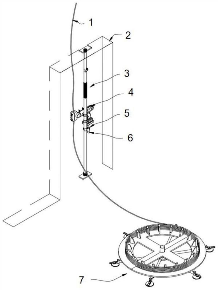
[0052] The wire laying and transmission method, the equipment mainly includes a telescopic rod 3, a wire laying and transmission device 4, and a wire coiling device. The wire laying and transmission device 4 is connected to the telescopic rod 3 through a connecting device. The rod is used as a support point to quickly erect the wire laying and transmission device 4 for wire transmission, and replace most of the manual work by machinery to realize the rapid transmission and collection of wires from the general power distribution room on the upper floor to the power distribution room on the next floor. Quickly collect wires through the coiling device to avoid interweaving of wires and messy construction site;

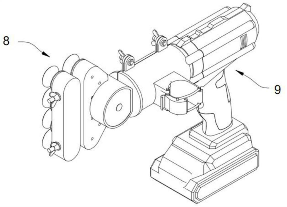
[0053] The wire laying and transmission device 4 includes a transmission mechanism 8 and a drive mechanism 9. The transmission mechanism 8 includes an output shaft 22, and one end of the output shaft 22 is connected with groups of bevel gear sets of different sizes, and th...

Embodiment 2

[0055] Based on embodiment 1, embodiment 2 further defines the wire laying transmission line device:

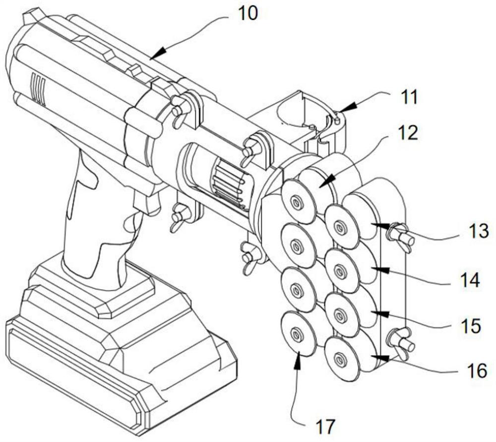
[0056] Further, in the above-mentioned wire laying and transmission method, the two sides of the main gear 30 are respectively meshed with gear one 31 and gear two 32, and gear three 33 and gear four 34 are meshed with gear one 31, and gear two 32 are meshed with gear two. Engagement has gear five 35 and gear six 36, and gear three 33, gear four 34, gear five 35 and gear six 36 connect drive wheel one 12, drive wheel two 28, drive wheel three 29 and drive wheel four 17 respectively, and drive Wheel one 12, driving wheel two 28, driving wheel three 29 and driving wheel four 17 rolling friction connections are pinch wheel one 13, pinch wheel two 14, pinch wheel three 15 and pinch wheel four 16.

[0057] Further, the above-mentioned wire laying and transmission method also includes a housing 26, the housing 26 mainly includes two parts, one part of the housing is connected with ...

Embodiment 3

[0065] Based on Embodiment 1 or Embodiment 2, Embodiment 3 further defines the structure of the telescopic rod:

[0066] Further, in the above-mentioned wire laying and transmission method, the telescopic rod 3 includes a plurality of rod bodies with gradually smaller diameters, which are divided into rod body one 43, rod body two 44 and rod body three 45 from bottom to top, and the plurality of rod bodies can be composed of telescoping structure.

[0067] Further, the above-mentioned wire laying and transmission method also includes a locking clip 47, the locking clip 47 is composed of a sleeve 50, a fastening bolt 54, a locking clip pin shaft 51 and a handle 53, wherein the sleeve 50- The side opening forms two parts on the left and right, wherein a part of the inner wall is connected with a connecting rod, and the other part is provided with a through hole at a position suitable for the connecting rod. Rotately connected with the handle 53, the side of the handle 53 close ...


PUM


Abstract

The invention provides a wire laying and transmission method. The equipment mainly includes a telescopic rod, a wire laying and transmission device, and a wire coiling device. The wire laying and transmission device is connected to the telescopic rod through a connecting device. The wire laying and transmission device includes a transmission mechanism and a driving mechanism. The small bevel gear is fixedly connected to the output shaft of the transmission mechanism, and the large bevel gear is connected to the small bevel gear for vertical rotation. One side of the large bevel gear is connected. There is a main gear, and the main gear drives the gear set to drive the driving wheel to rotate, and the corresponding part of the driving wheel is connected with a driven pressure wheel, and the wire is between the driving wheel and the pressure wheel. This method is mainly to install the telescopic rod as a support point at the door opening, quickly erect the wire laying transmission device, and then use its dragging ability to carry out wire transmission, mechanically replace most of the labor, and realize the wire from the upper layer to the general power supply. The power distribution room quickly transmits and gathers lines to the power distribution room on the next floor. At the same time, the cable hub quickly collects the wires to avoid the interweaving of wires and the messy construction site.

Description

technical field [0001] The invention relates to the technical field of wire transmission coils, in particular to a wire laying and transmission method. Background technique [0002] The most common indoor dynamic lighting systems in buildings include household power supplies, distribution boxes, wiring, lamps, sockets, switches and power supplies for various equipment. The wiring mainly depends on wires of various specifications. The 220V voltage adopts single-phase two-wire, single-wire three-wire, and the 380V voltage adopts three-phase four-wire and three-phase five-wire. Bundle the wires running in the same direction during wiring, which can reduce the occupied space and facilitate inspection, testing and maintenance. Among them, the wiring and collection lines with heavy workload are often transported from the general power distribution room on the upper level to the lower level power distribution room, and the length of laying is tens of meters, which is completely pu...

Claims


Application Information

Patent Timeline
Patent Type & Authority Patents(China)
IPC IPC(8): B65H51/10B65H49/30H02G1/06
CPCB65H51/10B65H49/30H02G1/06B65H2701/34
Inventor 夏春黎耀南郑运洪剪元香杨佳华
Owner CHINA FIRST METALLURGICAL GROUP
Why Eureka
Try Eureka