Combined grounding wire assembly

A grounding wire and combined technology, applied in the direction of connection, conductive connection, electrical component connection, etc., can solve problems such as laborious, increased safety risks of climbing operations, and small space in 10kV switch cabinets, so as to ensure the safety of equipment and personal safety , save recycling and sorting time, and avoid the effect of climbing operation risks

Inactive Publication Date: 2017-05-31
STATE GRID CORP OF CHINA +1
View PDF5 Cites 0 Cited by
  • Summary
  • Abstract
  • Description
  • Claims
  • Application Information

AI Technical Summary

Problems solved by technology

[0002] In the daily maintenance work of on-site workers, the grounding wire is an essential device used to ground the power failure line to ensure the safety of personnel during the maintenance work. Its function is to prevent the equipment from suddenly receiving electricity to generate arcs and voltages, which will cause harm to the on-site workers. " The State Grid Corporation of China Electric Power Safety Work Regulations clearly stipulates that the ground wire must be hung during power outage operations. However, in the actual process of hanging the ground wire, it was found that due to the different heights of the power equipment, the complicated position of the ground wire suspension connection point, the difficult operation angle, and the site environment Due to poor conditions and other reasons, it is time-consuming and laborious to hang the ground wire, and it also has a high risk of safe operation. According to the survey, the traditional ground wire often encounters the following problems in field application:
[0003] 1. The traditional 10-35kV grounding wire group is generally composed of a single insulated operating rod connected to the grounding wire. The lengths are 25cm and 65cm respectively. The distance between the wire insulation poles is not enough and the grounding wire needs to be suspended from the height, which directly increases the safety risk of the climbing operation during the process of climbing
[0004] 2. When the traditional grounding wire is suspended in the 10-35kV switchgear, the space of the 10kV switchgear is too small. When using the traditional standard length grounding wire to hang the grounding wire, it often happens that the grounding wire operation rod is too long to hang the grounding wire smoothly.
[0005] 3. Due to the large difference in the structure of the installation point of the grounding wire of electrical equipment, the structure of the installation point is sometimes a wire type, sometimes a flat iron type, and the wire can be divided into a horizontal wire and a vertical wire, and the flat iron can be divided into a bridge type. Flat irons and flat irons, the installation of horizontal wires and flat irons is relatively easy, but the installation of vertical wires and bridge-type flat irons is very difficult, so some operating rod joints are often small in size when using conventional grounding wires. If it is not suitable, the suspended ground wire cannot be effectively fixed on the wire. If the wind swings or touches under the action of gravity, the ground wire hook is easy to fall off and hurt other electrical equipment and personnel, resulting in accidents.
[0006] 4. The traditional grounding wire group is that the operating rod and the grounding wire chuck are fixedly connected together and cannot be separated, which leads to time-consuming and laborious recovery of the grounding wire. At the same time, it is necessary to separate the insulating rod and the grounding wire test during the regular test. Time-consuming, labor-intensive, troublesome

Method used


Image

  • Combined grounding wire assembly
  • Combined grounding wire assembly
  • Combined grounding wire assembly

Examples


Embodiment Construction

[0025] The present invention will be further explained below in conjunction with specific embodiments and accompanying drawings.

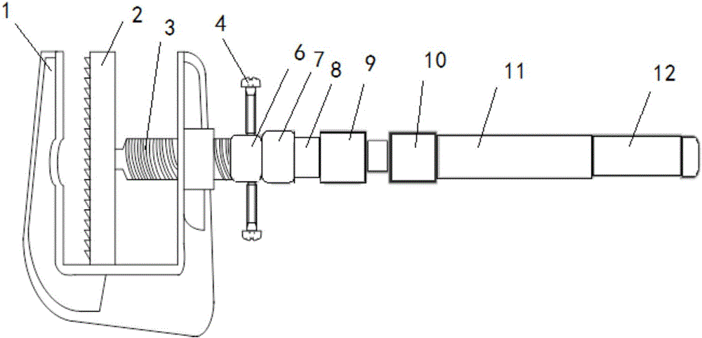
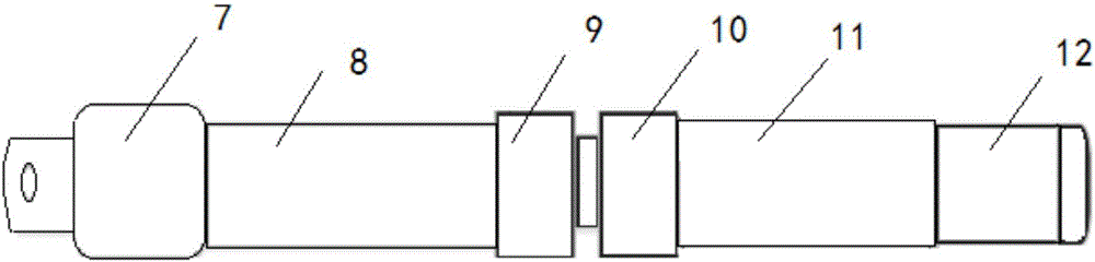
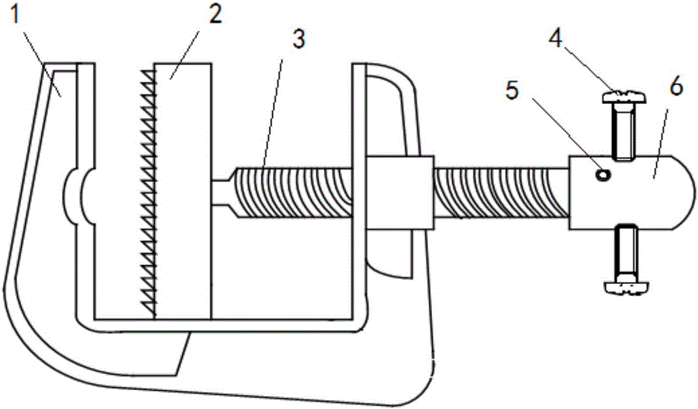
[0026] see figure 1 , the present invention includes the connecting clips and insulating rods connected in sequence, see image 3 , the wiring clip includes a U-shaped clamping mouth 1, the clamping part of the clamping mouth 1 is provided with a notch for clamping the line, the clamping mouth 1 is provided with a moving tongue 2, and the clamping part of the moving tongue 2 is provided with a Sawtooth structure, the moving tongue 2 is connected to one end of the screw 3, the screw 3 is threaded to the jaw 1, and the other end of the screw 3 is provided with a joint 6; see figure 2 , the insulating rod includes an insulating rod bayonet 7 connected to the joint 6, the insulating rod bayonet 7 is provided with a connecting piece, the joint 6 is provided with a slot for clamping the connecting piece, and the side walls of the joint 6 are located on...


PUM


Abstract

The invention discloses a combined grounding wire assembly, which aims to achieve the effect that the length of an operation rod can be freely adjusted and different models of jointing clamps can be freely replaced according to the hanging height of a grounding wire and the size of a joint position. The combined grounding wire assembly adopts the technical scheme that the combined grounding wire assembly comprises a jointing clamp and an insulation rod which are connected in sequence, wherein the jointing clamp comprises a U-shaped clamp mouth, a movable tongue piece is arranged in the clamp mouth and connected with one end of a screw rod, the screw rod and the clamp mouth are connected in a threaded manner, and a connector is arranged at the other end of the screw rod; and the insulation rod comprises an insulation rod bayonet connected with the connector, an upper insulation rod is connected with the insulation rod bayonet and sleeved in a lower insulation rod, the upper insulation rod can extend out of or retract into the lower insulation rod, and lock catches are arranged at the joint of the upper insulation rod and the lower insulation rod and used for fixing the upper insulation rod and the lower insulation rod.

Description

technical field [0001] The invention relates to the technical field of electric power engineering, in particular to a combined ground wire set. Background technique [0002] In the daily maintenance work of on-site workers, the grounding wire is an essential device used to ground the power failure line to ensure the safety of personnel during the maintenance work. Its function is to prevent the equipment from suddenly receiving electricity to generate arcs and voltages, which will cause harm to the on-site workers. " The State Grid Corporation of China Electric Power Safety Work Regulations clearly stipulates that the ground wire must be hung during power outage operations. However, in the actual process of hanging the ground wire, it was found that due to the different heights of the power equipment, the complicated position of the ground wire suspension connection point, the difficult operation angle, and the site environment Due to poor conditions and other reasons, it is...

Claims


Application Information

Patent Timeline
IPC IPC(8): H01R11/14
CPCH01R11/14
Inventor 陈永平豆河伟高伟蒋浩乔媛媛
Owner STATE GRID CORP OF CHINA
Why Eureka
Try Eureka