
Novel switch cabinet

A switchgear, a new type of technology, applied in the field of switchgear, can solve the problems of difficult flexible adjustment, narrow staff activities and work scope, troublesome installation and disassembly process, etc., to ensure stability and safety performance, increase activities and work range, the effect of improving the efficiency of installation and removal

Inactive Publication Date: 2017-05-31
JIANGSU JIANXIONG ELECTRIC CO LTD
View PDF0 Cites 0 Cited by
  • Summary
  • Abstract
  • Description
  • Claims
  • Application Information

AI Technical Summary

Problems solved by technology

[0003] The components in the existing switchgear are mainly connected to the inner wall of the switchgear. On the one hand, when installing and disassembling these components, the activities and work scope of the staff are relatively narrow, and the process of installation and disassembly is relatively troublesome. On the one hand, the placement of components in the switchgear is limited and it is difficult to adjust flexibly; in addition, the volume and weight of the switchgear are large, and it is difficult to move. Although the bottom of some existing switchgears is equipped with moving wheels, it is greatly reduced. After the switchgear is moved to the designated position, it is difficult to fix its relative position, and it is easy to slide, which affects the safety performance of the switchgear

Method used


Image

  • Novel switch cabinet
  • Novel switch cabinet
  • Novel switch cabinet

Examples


Embodiment Construction

[0019] The present invention will be further explained below in conjunction with the accompanying drawings and specific embodiments. It should be understood that the following specific embodiments are only used to illustrate the present invention and are not intended to limit the scope of the present invention.

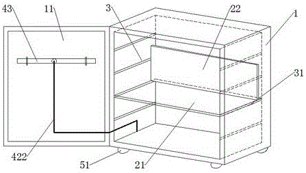
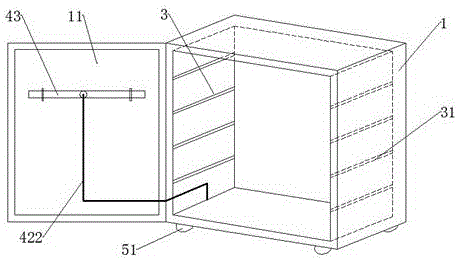
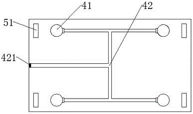
[0020] like Figure 1-4 As shown, a new type of switch cabinet includes a switch cabinet body 1 and a supporting device 2. At least two bar-shaped chute groups 3 are arranged in the switch cabinet body 1 from top to bottom, and each bar-shaped chute group 3 includes Two left and right symmetrical strip chutes 31 are arranged on the left and right side walls inside the switchgear body 1, and the plane formed by the two strip chutes 31 of each strip chute group 3 is parallel to the ground, supporting Device 2 comprises base plate 21 and component plug-in plate 22 vertically arranged on base plate 21, the both sides of base plate 21 can slide in two bar-shaped chute 31 o...


PUM


Abstract

The invention provides a novel switch cabinet, which comprises a switch cabinet body and a bearing device. At least two strip-shaped chute groups are arranged in the switch cabinet body from top to bottom; each strip-shaped chute group comprises two strip-shaped chutes bilaterally symmetrically formed on both left and right side walls inside the switch cabinet body; the bearing device comprises a bottom plate and a part insertion board vertically arranged on the bottom plate; the part insertion board is arranged on one side of the bottom plate, which is close to the rear wall inside the switch cabinet body; a plane where the part insertion board is positioned is in parallel to a plane where the rear wall of the switch cabinet body is positioned; a supporting device and a moving device are arranged at the bottom of the switch cabinet body. The novel switch cabinet has the advantages that parts in the switch cabinet are convenient to mount and disassemble, and mounting and disassembling efficiency of the parts is improved; a mounting height of the bearing device in the switch cabinet can be flexibly regulated according to actual requirements of the parts for placement; after the switch cabinet is moved to a designated position, a relative position of the switch cabinet is fixed by the supporting device, and the switch cabinet is prevented from sliding, so that stability and safety performance of the switch cabinet are ensured.

Description

technical field [0001] The invention relates to the technical field of switch cabinets, in particular to a novel switch cabinet. Background technique [0002] The switch cabinet is a kind of electrical equipment. The outside line of the switch cabinet first enters the main control switch in the cabinet, and then enters the sub-control switch. Each branch is set according to its needs. Its main function is to generate, transmit, distribute and convert power in the power system. During the process, switch, control and protect electrical equipment. The components in the switch cabinet are mainly composed of circuit breakers, disconnectors, load switches, operating mechanisms, transformers and various protection devices. Such as instruments, automatic controls, motor magnetic switches, various AC contactors, etc., some also have high-voltage room and low-voltage room switch cabinets, high-voltage busbars, such as power plants, etc. load shedding. [0003] The components in th...

Claims


Application Information

Patent Timeline
Patent Type & Authority Applications(China)
IPC IPC(8): H02B1/52H02B1/30
CPCH02B1/52H02B1/303
Inventor 唐伯桂
Owner JIANGSU JIANXIONG ELECTRIC CO LTD
Learn More