Insulator replacement device

A technology of insulators and clamps, applied in the direction of overhead lines/cable equipment, etc., can solve the problems of increasing the time and risk of aerial work, unable to guarantee the fit of the clamp head, inconvenient disassembly and assembly, etc., to achieve good promotion prospects and practical value, The effect of improving stability and improving connection strength

Active Publication Date: 2017-05-31
国网河南省电力公司超高压公司 +1
View PDF11 Cites 2 Cited by
  • Summary
  • Abstract
  • Description
  • Claims
  • Application Information

AI Technical Summary

Problems solved by technology

[0005] When the above two structures are in use, the size of the jig head in contact with the steel cap of the insulator is fixed, but the size of the steel caps produced by different manufacturers, different models, and different batches is different, and the chuck head is too small when used. If it is too large or too l

Method used


Image

  • Insulator replacement device
  • Insulator replacement device
  • Insulator replacement device

Examples


Embodiment 1

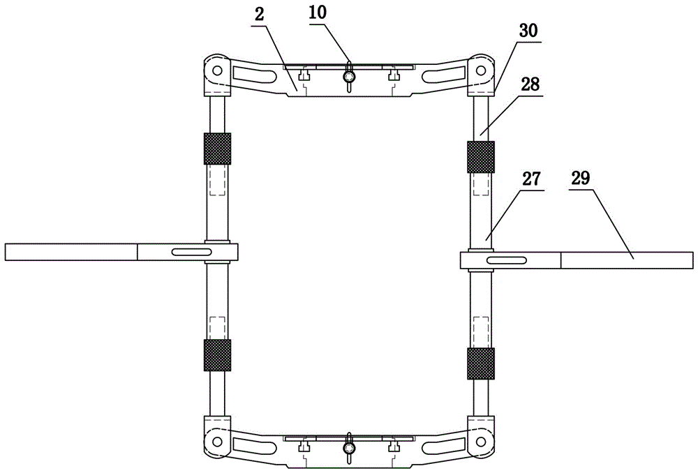
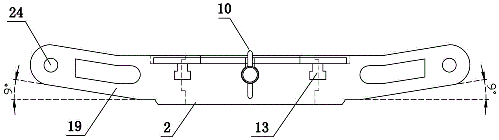
[0044] like Figure 1 to Figure 9 As shown, the present invention includes a fixture and a length adjustment mechanism, and the fixture is two including an upper fixture and a lower fixture, and both the upper fixture and the lower fixture include a fixedly connected first clamping plate 1 and a second clamping plate 2 The opposite end surfaces of the first clamping plate 1 and the second clamping plate 2 are arc-shaped and enclose a columnar cavity 3 for accommodating the insulator steel cap. The upper end surface of the first clamping plate 1 is provided with a first receiving groove 4, and the second The upper end surface of clamping plate 2 offers the second accommodation groove 5, and the first accommodation groove 4 and the second accommodation groove 5 are semi-circular structure and both surround and form the annular accommodation groove, the first accommodation groove 4 is slidingly set and first The first adjusting ring 6 matching the receiving groove 4, the second a...

Embodiment 2

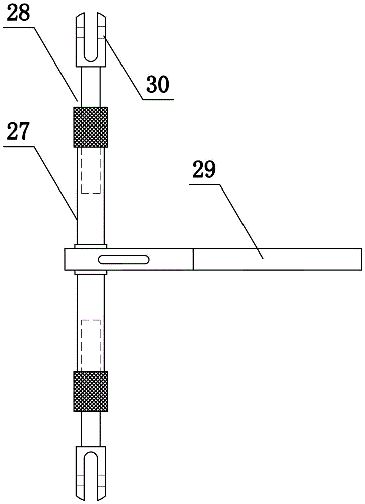
[0052] The structure of this embodiment is basically the same as that of Embodiment 1, the difference is: as Figure 10 to Figure 12 As shown, an extension rod 31 is set between the left length adjustment mechanism and the upper jig, and a tension sensing module 32 is set between the right length adjustment mechanism and the upper jig. The output end of the tension sensing module 32 is electrically connected to the control module, and the control module is electrically connected to the The display module 33 and the control module (not shown) are integrated inside the display module 33 . It should be pointed out that both ends of the extension tube 31 and the tension sensing module 32 are provided with connecting parts to connect with the length adjusting mechanism and the fixture.

Embodiment 3

[0054] The structure of this embodiment is basically the same as that of Embodiment 1, the difference is: as Figure 13 As shown, the side end surfaces of the first clip 1 and the second clip 2 are provided with a third receiving groove 25, and a positioning plate 26 is slidably arranged in the third receiving groove 25, and a screw thread matched with the limit nut 10 is provided on the positioning plate 26. A through hole is provided on the connecting plate 9. When this structural design is in use, the positioning plate 26 is pressed outwardly in the third receiving groove 25 by turning the limit nut 10, so as to realize the fixing of the limit nut 10 to the connecting plate 9. The nut 10 is connected with the threaded through hole on the connecting plate 9 , and this structural design has a better and more stable fixing effect on the first adjusting ring 6 and the second adjusting ring 7 .


PUM


Abstract

The invention discloses an insulator replacement device which comprises a clamp apparatus and a length regulation mechanism. The clamp apparatus comprises a first clamping plate and a second clamping plate which are fixedly connected; the first clamping plate and the second clamping plate are enclosed to form a cylindrical cavity; a first accommodating groove is formed on the upper end face of the first clamping plate; a second accommodating groove is formed on the upper end face of the second clamping plate; a first regulating ring is arranged in a sliding mode in the first accommodating groove; a second regulating ring is arranged in a sliding mode in the second accommodating groove; the center lines of arc holes interact with the center lines of the ring-shaped accommodating grooves; through slots are arranged on the side end faces of the first clamping plate and the second clamping plate; extension directions of the through slots point to the central axis of the cylindrical cavity; the upper ends of the through slots are communicated with the ring-shaped accommodating grooves; limiting pillars are arranged in a sliding mode in the through slots; limiting pins are vertically arranged at the upper end faces of the limiting pillars; the upper ends of the limiting pins extend out of the arc holes. According to the insulator replacement device disclosed by the invention, by regulating the positions of the arc holes, sliding of the limiting pillars in the through slots is implemented; and the insulator replacement device can be used for the replacement work of all types of suspended insulator strings in a substation.

Description

technical field [0001] The invention belongs to the technical field of electric facility maintenance, and in particular relates to an insulator replacement device. Background technique [0002] The amount of suspension insulator strings in the substation is huge, and the suspension insulator strings are in the open environment for a long time. Under the influence of environmental factors such as wind, sun and sun, the internal stress of the insulators will be unbalanced, resulting in low zero value of the insulators and even structural damage. The damage defects of suspension insulator strings in substations are increasing day by day. At present, there is no special replacement tool suitable for the suspension insulator strings in the station. When replacing the suspension insulator strings in the station, it can only be replaced by the traditional method, that is, the hand hoist is used to pull the wires and clamps, so that the suspension insulator strings are in the In th...

Claims


Application Information

Patent Timeline
IPC IPC(8): H02G1/02
CPCH02G1/02
Inventor 郭栋孙惠涛尹飞李景昊李忠民张建辉陶留海高嵩崔磊樊建军郭文博陈雷孙超刘维陈鹏秦岭吴小磊张利柳青巩持恒石生智武臻崔凤庆
Owner 国网河南省电力公司超高压公司
Why Eureka
Try Eureka