cable clamp

A cable clamp and cable technology, applied in the direction of overhead line/cable equipment, etc., can solve the problem of single use performance of cable clamp, and achieve the effect of improving service life, preventing damage and preventing misoperation

Active Publication Date: 2018-08-03
国网浙江乐清市供电有限公司第二名称:乐清市供电局 +3
View PDF8 Cites 0 Cited by
  • Summary
  • Abstract
  • Description
  • Claims
  • Application Information

AI Technical Summary

Problems solved by technology

[0003] The technical problem to be solved by the present invention is to provide a cable clamp to solve the problem of single performance of the existing cable clamp

Method used


Image

  • cable clamp
  • cable clamp
  • cable clamp

Examples


Embodiment Construction

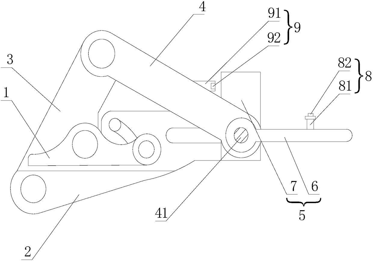
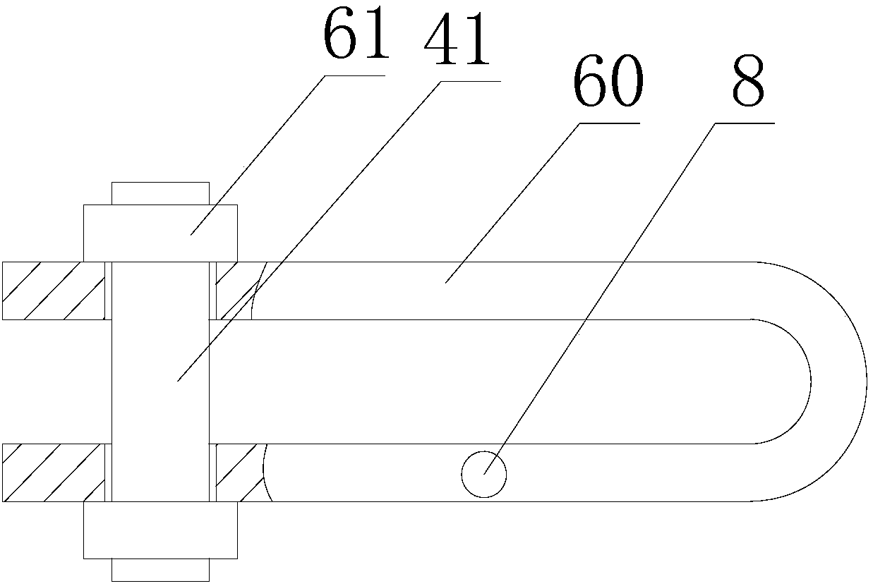
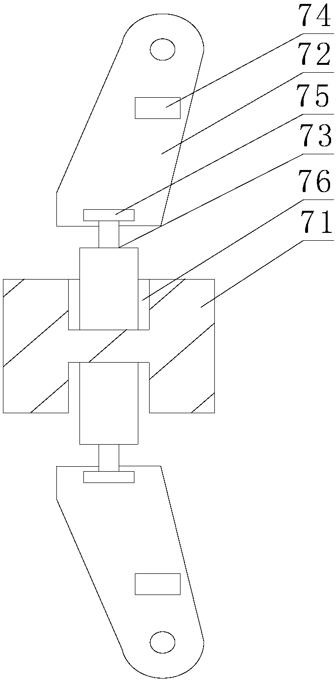
[0019] Such as figure 1 , figure 2 , image 3 As shown, the cable clamp includes an upper splint 1, a lower splint 2, a pressure plate 3 and a pull plate 4. One end of the upper splint 1 is rotatably connected to the lower splint 2, and the other end of the upper splint 1 is rotatably connected to the pressure plate 3. The pressure plate One end of 3 is rotatably connected to the lower splint 2, the other end of the pressing plate 3 is rotatably connected to one end of the pull plate 4, and the other end of the pull plate 4 is slidably connected to the lower splint 2 through the connecting shaft 41, between the upper splint 1 and the lower splint 2 Form the clamping hole of the cable, the pulling assembly 5 that is connected with the other end of the control pulling plate 4 to slide on the lower clamping plate 2 on the pulling plate 4, the pulling assembly 5 includes a first pulling part 6 and a second pulling part 7, the first pulling part 6 is arranged on the connecting s...


PUM


Abstract

The invention relates to a cable clamping device. The cable clamping device comprises an upper clamping plate, a lower clamping plate, a pressing plate and a pulling plate, wherein one end of the upper clamping plate is rotationally connected with the lower clamping plate while the other end of the upper clamping plate is rotationally connected with the pressing plate; one end of the pressing plate is rotationally connected with the lower clamping plate while the other end of the pressing plate is rotationally connected with one end of the pulling plate, and the other end of the pulling plate is glidingly connected with the lower clamping plate through a rotary shaft; a clamping hole for a cable is formed between the upper clamping plate and the lower clamping plate; the pulling plate is connected with a pulling assembly which is used for controlling the other end of the pulling plate to slide on the lower clamping plate; and the pulling assembly comprises a first pulling part and a second pulling part. The cable clamping device has the advantages as follows: the pulling assembly comprises the first pulling part and the second pulling part, so that the first pulling part or the second pulling part can be selected to pull the pulling plate according to different working occasions; the practical performance of the overall cable clamping device can be improved; the cable clamping device can be applicable to different operators in operation; and in addition, diversified selection of the pulling assembly, rapid operation of the pulling plate, and the simple structure can be realized.

Description

technical field [0001] The present invention relates to cable clamps. Background technique [0002] With the improvement of my country's comprehensive national strength and the acceleration of modernization, the construction of various large-scale public facilities is booming, and the wide application of electric power makes the application of transmission lines more extensive, such as gymnasiums, convention centers, hangars, theaters and other large-span The space also has new requirements for the power transmission releasing, tightening and withdrawing devices. The existing clamping device includes an upper splint, a lower splint, a pressing plate and a pulling plate. Sliding, thereby driving the pressing plate to press down the splint to realize the clamping of the wire. However, during the pulling process of the existing pulling plate, the operator’s work intensity is high, and the pulling components connected to the pulling plate are single, which cannot be adapted to dif...

Claims


Application Information

Patent Timeline
Patent Type & Authority Patents(China)
IPC IPC(8): H02G1/04
CPCH02G1/04
Inventor 谢宾章雷邵文晋吴信文胡茜潘登潘锦良
Owner 国网浙江乐清市供电有限公司第二名称:乐清市供电局
Why Eureka
Try Eureka