Linear compressor

A linear compressor and cylinder technology, applied in the field of compressors, can solve problems such as large axial size, achieve the effects of reducing axial size, avoiding radial displacement, and ensuring stability and reliability

Pending Publication Date: 2021-08-13
TECHNICAL INST OF PHYSICS & CHEMISTRY - CHINESE ACAD OF SCI
View PDF0 Cites 0 Cited by
  • Summary
  • Abstract
  • Description
  • Claims
  • Application Information

AI Technical Summary

Problems solved by technology

[0005] The embodiment of the present invention provides a linear compressor, which is used to solve the problem that the existing linear compressor has a large axial dimension, and has a large contact sliding friction between the piston and the cylinder, and must be oil-lubricated.

Method used


Image

  • Linear compressor
  • Linear compressor
  • Linear compressor

Examples


Embodiment 1

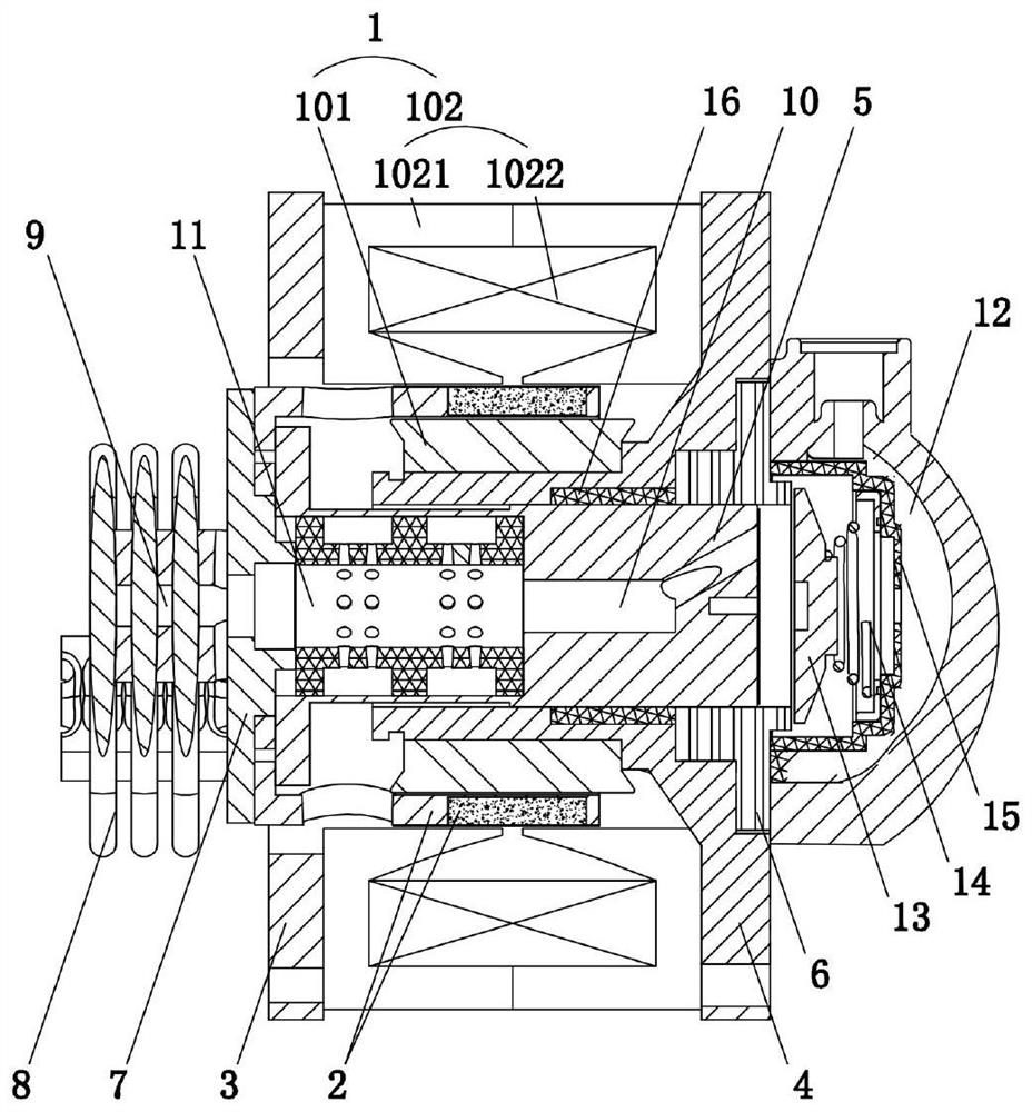
[0050] Such as figure 1 and figure 2 As shown, the stator 1 in this embodiment includes an inner stator 101 and an outer stator 102 coaxially arranged, and a cylindrical air gap is formed between the inner stator 101 and the outer stator 102; the mover 2 is embedded in the cylindrical air gap , including a coaxially connected mover skeleton and an annular permanent magnet, wherein the mover skeleton is in a cup-shaped structure; the piston 5 is coaxially located inside the mover 2, and the first end of the piston 5 is connected to the mover skeleton through a gasket 7 One end away from the annular permanent magnet, thus, the piston 5 and the mover 2 form an integral moving part.

[0051] Specifically, the first fixed seat 3 and the second fixed seat 4 are coaxially arranged at both ends of the stator 1, so that the inner stator 101, the mover 2 and the outer stator 102 are arranged in sequence in the radial direction, and the inner fixed The two ends of the sub 101 and the ...

Embodiment 2

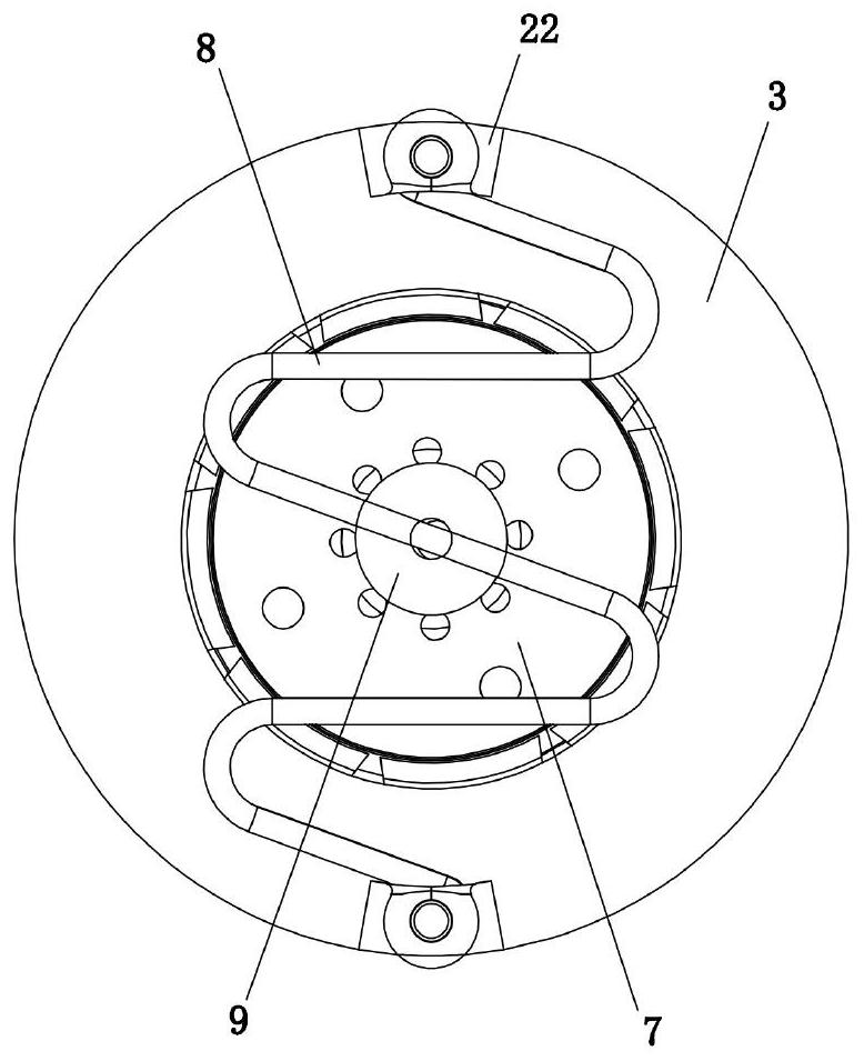
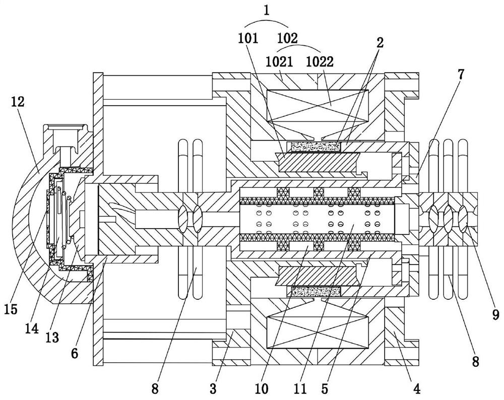
[0063] Such as image 3 As shown, this embodiment is a further improvement based on Embodiment 1. The difference is that in this embodiment, leaf spring groups 8 are provided on both sides of the stator 1, that is, the middle part of the leaf spring group 8 on the left side of the stator 1 is connected. The piston 5 on the corresponding side, the free end of the leaf spring group 8 is connected to the first fixed seat 3, the middle part of the leaf spring group 8 on the right side of the stator 1 is connected to the end of the corresponding side piston 5, the free end of the leaf spring group 8 It is connected to the second fixed seat 4 , wherein the cylinder 6 and its corresponding exhaust device can be arranged on the first fixed seat 3 or on the second fixed seat 4 , which is not specifically limited.

[0064] As a result, the two sets of leaf springs 8 jointly provide sufficient radial support for the piston 5 from both sides of the piston 5, effectively avoiding the pheno...

Embodiment 3

[0066] Such as Figure 4 As shown, this embodiment is a further improvement based on Embodiment 1, and the difference is that the gas bearing sleeve 16 shown in Embodiment 1 is not needed in the linear compressor shown in this embodiment. Since in embodiment 1, a leaf spring group 8 is provided on one side of the stator 1 to provide better radial support for the piston 5 in the process of reciprocating movement in the cylinder 6, thereby greatly reducing the size of the piston 5 and the cylinder. 6, the present embodiment can also use oil lubrication to further reduce the contact friction between the piston 5 and the cylinder 6, and ensure a longer service life of the linear compressor.

[0067] Thus, in the design of the specific scheme, the oil pump 17 and the oil injection channel 18 can be set, and the oil pump 17 and the cylinder 6 are jointly installed on the second fixed seat 4. One end of the oil injection channel 18 communicates with the oil delivery end of the oil pu...


PUM


Abstract

The invention relates to the technical field of compressors, and discloses a linear compressor. The linear compressor comprises a stator, a rotor, a piston and an air cylinder which are coaxially arranged, and further comprises a flat spring arranged at one end or two ends of the stator, and the flat spring comprises a plurality of free ends. The first end of the piston is connected with the rotor, and the second end of the piston is inserted into the air cylinder. The middle of the flat spring is connected with the piston, each free end of the flat spring is connected with the corresponding end of the stator, or at least one free end of the flat spring is connected with the piston, and other free ends of the flat spring are connected with the corresponding ends of the stator. The linear compressor is simple in structure, radial positioning installation is carried out on the piston through the low-cost flat spring, radial displacement of the piston is effectively avoided, non-contact reciprocating motion of the piston in the air cylinder is achieved, oil-free lubrication or oil lubrication of the linear compressor can be achieved, the working noise of the linear compressor is reduced, and the axial size is greatly reduced.

Description

technical field [0001] The invention relates to the technical field of compressors, in particular to a linear compressor. Background technique [0002] The linear compressor is a piston compressor using a linear motor. It has the advantages of compact structure, light weight, no oil or less lubricating oil, and excellent variable capacity characteristics. Therefore, it has been more and more widely used and has become a small A main development direction of high-efficiency compressors for refrigeration equipment. [0003] The linear motor includes a stator and a mover, and the mover performs linear reciprocating motion along the axial direction. As one of the typical structures of linear motors, the moving magnet linear oscillation motor has a structure in which a magnetic material is installed on the circumference of the excitation coil to form a magnetic circuit structure with a cylindrical air gap concentric with the excitation coil. The inner and outer stators form an ...

Claims


Application Information

Patent Timeline
Patent Type & Authority Applications(China)
IPC IPC(8): F04B35/04F04B39/00F04B39/02F04B39/10H02K7/14H02K16/00H02K33/00H02K41/02
CPCF04B35/04F04B39/0005F04B39/0027F04B39/0292F04B39/10H02K7/14H02K16/00H02K33/00H02K41/02
Inventor 唐明生邹慧明田长青
Owner TECHNICAL INST OF PHYSICS & CHEMISTRY - CHINESE ACAD OF SCI
Why Eureka
Try Eureka