
Steel mesh bridge

A bridge and steel mesh technology, applied in the direction of electrical components, etc., can solve the problems of packaging and handling, inconvenient installation and transportation, difficult bolt connection and fastening, long construction time, etc. short time effect

Active Publication Date: 2017-05-31
江苏国美钢网桥架有限公司
View PDF8 Cites 0 Cited by
  • Summary
  • Abstract
  • Description
  • Claims
  • Application Information

AI Technical Summary

Problems solved by technology

[0002] In the prior art, the connection parts of the mesh bridge generally use independent connecting pieces to fasten and connect with bolts, and the connection and fastening of bolts on the mesh bridge is relatively difficult; the independent connecting pieces need to be surface cleaned, and various processes such as adding an anti-corrosion layer The process is complicated, and the number of parts is large, the production and manufacturing are cumbersome, the construction time is long, and the packaging, handling, installation and transportation are inconvenient

Method used


Image

  • Steel mesh bridge
  • Steel mesh bridge
  • Steel mesh bridge

Examples


Embodiment Construction

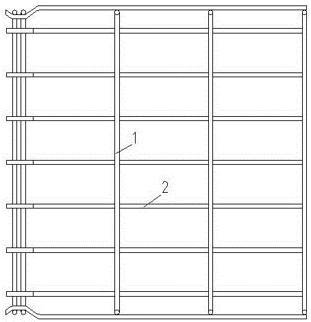
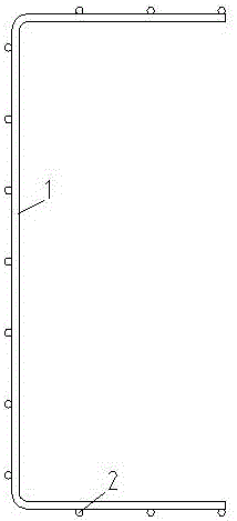
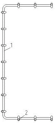
[0018] As shown in the figure, a steel mesh bridge includes several U-shaped beams 1, and several longitudinal ribs 2 fixedly connected to the U-shaped beams 1, and the connection point between the U-shaped beams 1 and the longitudinal ribs 2 is located inside the longitudinal ribs 2; At least one end of the steel mesh bridge is the head end with two U-shaped beams 1 that are relatively close to each other. A section of longitudinal rib 2 connected to the two U-shaped beams 1 at the head end bends inward to form a groove so that the two U-shaped beams 1 at the head end The U-shaped beam 1 is in the groove of the longitudinal rib 2, that is, the connection point between the two U-shaped beams 1 at the head end and the groove section of the longitudinal rib 2 is located outside the longitudinal rib 2; when connecting with the conventional steel mesh bridge, the groove of the longitudinal rib 2 The section is located inside the U-shaped beam 3 at the end of the conventional bridge...


PUM


Abstract

The invention provides a steel mesh bridge consisting of a plurality of U-shaped cross beams and longitudinal ribs, wherein the connection points of the U-shaped cross beams and the longitudinal ribs are located on inner sides of the longitudinal ribs; at least one end of the steel mesh bridge is a head end provided with two U-shaped cross beams with a closer distance, a segment of the longitudinal rib connected with the two U-shaped cross beams on the head end is bent inward to form a groove, so that the two U-shaped cross beams on the head end are located in the groove of the longitudinal rib, the parts of two side edges and bottom margins of the two U-shaped cross beams on the head end of the steel mesh bridge located between two adjacent longitudinal ribs are provided with projections protruding to the outer sides, and the projections can limit the two side edges and bottom margins of the two U-shaped cross beams of the conventional steel mesh bridge so as to prevent drop-out; and no connection strap needs to be additionally arranged, thereby being convenient to install and connect, small in mass and volume, reliable to connect, convenient to install and transport, small in the number of parts and components, simple in production and manufacture processes, short in engineering construction time and high in economic benefit.

Description

technical field [0001] The invention relates to a steel net bridge, which is specifically applied to cable laying in power transmission and transformation equipment in the electric power industry. Background technique [0002] In the prior art, the connection parts of the mesh bridge generally use independent connecting pieces to fasten and connect with bolts, and the connection and fastening of bolts on the mesh bridge is relatively difficult; the independent connecting pieces need to be surface cleaned, and various processes such as adding an anti-corrosion layer The processing and process are complicated, and the number of parts is large, the production and manufacturing are cumbersome, the construction time is long, and the packaging, handling, installation and transportation are inconvenient. Contents of the invention [0003] The technical problem to be solved by the present invention is to provide a steel mesh bridge that can be quickly connected, easy to operate, a...

Claims


Application Information

Patent Timeline
Patent Type & Authority Applications(China)
IPC IPC(8): H02G3/04
CPCH02G3/0456
Inventor 包正国
Owner 江苏国美钢网桥架有限公司
Learn More