Manufacturing method for laminated body
A manufacturing method and laminated body technology, applied in semiconductor/solid-state device manufacturing, chemical instruments and methods, lamination, etc., can solve problems such as light-emitting layer, electrode degradation, and poor light emission of components, and achieve the effect of suppressing damage
- Summary
- Abstract
- Description
- Claims
- Application Information
AI Technical Summary
Problems solved by technology
Method used
Image
Examples
no. 1 Embodiment approach
[0055] As follows, while referring to Figure 1~4 The manufacturing method of the laminated body which concerns on 1st Embodiment of this invention is demonstrated. In addition, in all the following drawings, in order to make a drawing easy to see, the dimension, ratio, etc. of each component are made to differ suitably.
[0056] [Laminate]
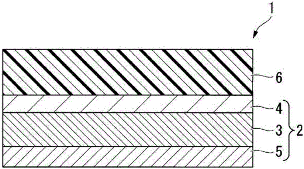
[0057] figure 1 It is a schematic diagram which shows an example of the laminated body manufactured in the manufacturing method of the laminated body of this embodiment. The laminated body 1 has a laminated film 2 and an adhesive layer 6 formed on one surface of the laminated film 2 .
[0058] (laminated film)
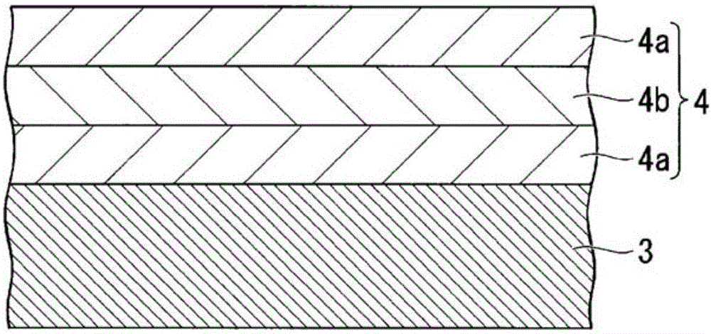
[0059] In the laminated body 1 of the present embodiment, the laminated film 2 has a base material 3, a film layer 4 formed between the base material 3 and an adhesive layer 6, and a film layer provided on the base material 3 and provided with the film layer 4. Curl suppression layer 5 on the opposite side.
[0060] That is,...
no. 2 Embodiment approach
[0196] Figure 5 It is explanatory drawing of the manufacturing method of the laminated body of 2nd Embodiment of this invention. The manufacturing method of the laminated body of this embodiment is partly common to the manufacturing method of the laminated body of 1st Embodiment, and the process of forming an adhesive layer differs. Therefore, in the present embodiment, the same reference numerals are attached to the same components as those in the first embodiment, and detailed description thereof will be omitted.
[0197] (Process of forming an adhesive layer)
[0198] Figure 5 It is an explanatory drawing showing the process of forming an adhesive layer in this embodiment, and it is a schematic diagram of the manufacturing apparatus 200 which implements the process of forming an adhesive layer.
[0199] The manufacturing apparatus 200 shown in the figure is equipped with the 1st unwinding roll 110, the winding roll 120, the surface treatment apparatus 150, the coating ...
Embodiment 1
[0254] The laminated film and transparent double-sided adhesive tape (manufactured by Lintec Corporation, TL-430S-06, 30 μm thick) were bonded together using a roller with the following tension applied, respectively, to manufacture the laminated body of Example 1. At this time, a transparent double-sided pressure-sensitive adhesive tape was attached to the film layer side of the laminated film.
[0255] It should be noted that the transparent double-sided adhesive tape corresponds to the "adhesive film 8A" in the above-mentioned embodiment, and the adhesive layer of the transparent double-sided adhesive tape corresponds to the "adhesive layer 6A" and "adhesive layer 6A" in the above-mentioned embodiment. Connect layer 6".
[0256] (fitting conditions)
[0257] Tension per unit cross-sectional area of laminated film: 39 N / mm 2
[0258] Tension per unit cross-sectional area of transparent adhesive double-sided tape: 0.1N / mm 2
PUM
| Property | Measurement | Unit |
|---|---|---|
| thickness | aaaaa | aaaaa |
Abstract
Description
Claims
Application Information
 - R&D
- Intellectual Property
- Life Sciences
- Materials
- Tech Scout
- Unparalleled Data Quality
- Higher Quality Content
- 60% Fewer Hallucinations
Browse by: Latest US Patents, China's latest patents, Technical Efficacy Thesaurus, Application Domain, Technology Topic, Popular Technical Reports.
© 2025 PatSnap. All rights reserved.Legal|Privacy policy|Modern Slavery Act Transparency Statement|Sitemap|About US| Contact US: help@patsnap.com


