
Plasma cleaning equipment for semiconductors

A plasma cleaning and semiconductor technology, which is applied in plasma, semiconductor/solid-state device manufacturing, transportation and packaging, etc., can solve the problems of large size, complex structure, difficult production and operation, etc., and achieve reduced size, simple device structure and logistics management easy effect

Active Publication Date: 2020-06-19
VISIONSEMICON CO LTD
View PDF4 Cites 0 Cited by
  • Summary
  • Abstract
  • Description
  • Claims
  • Application Information

AI Technical Summary

Problems solved by technology

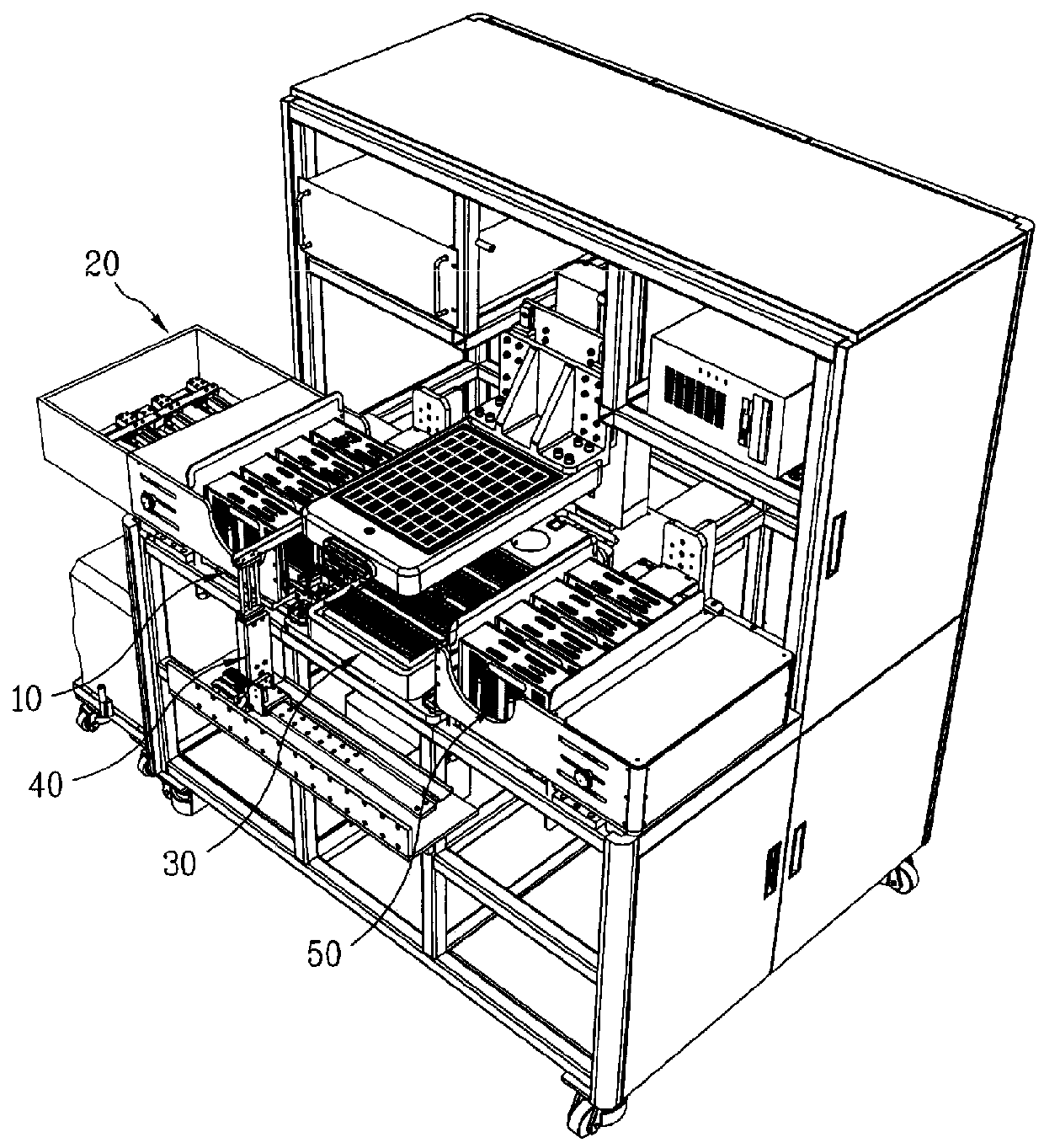
[0007] But the above-mentioned traditional plasma cleaning device must have the loading part 10 and the first transfer device 20 that will transfer the semiconductor accessories to the plasma cleaning head 30, and the second transfer device 40 and the second transfer device 40 that will transfer the cleaned semiconductor accessories to the rear. The unloading part 50 has a large specification and a complicated structure
[0008] In addition, the above-mentioned traditional plasma cleaning device is different from the material box loaded with semiconductor components before cleaning and the material box loaded with semiconductor components after cleaning. It is necessary to completely control the flow of semiconductor components through an automatic control program, and there are problems in making and using them.

Method used


Image

  • Plasma cleaning equipment for semiconductors
  • Plasma cleaning equipment for semiconductors
  • Plasma cleaning equipment for semiconductors

Examples


Embodiment Construction

[0022] In order to make the purpose, technical solutions and advantages of the embodiments of the present invention more clear, the technical solutions in the embodiments of the present invention will be clearly and completely described below in conjunction with the drawings in the embodiments of the present invention. The terms or words used in the specification and claims are, in principle, properly defined by the inventors in order to describe their own invention in the best way, and therefore should be interpreted with meanings and concepts consistent with the technical solution of the present invention.

[0023] The following is a detailed description in conjunction with an embodiment of the present invention. The same symbol is used for the same structure, and the description mainly revolves around different parts, so as to avoid repetition and ensure clarity in description.

[0024] Such as Figure 2 to Figure 5 As shown, the composition of the semiconductor plasma clea...


PUM


Abstract

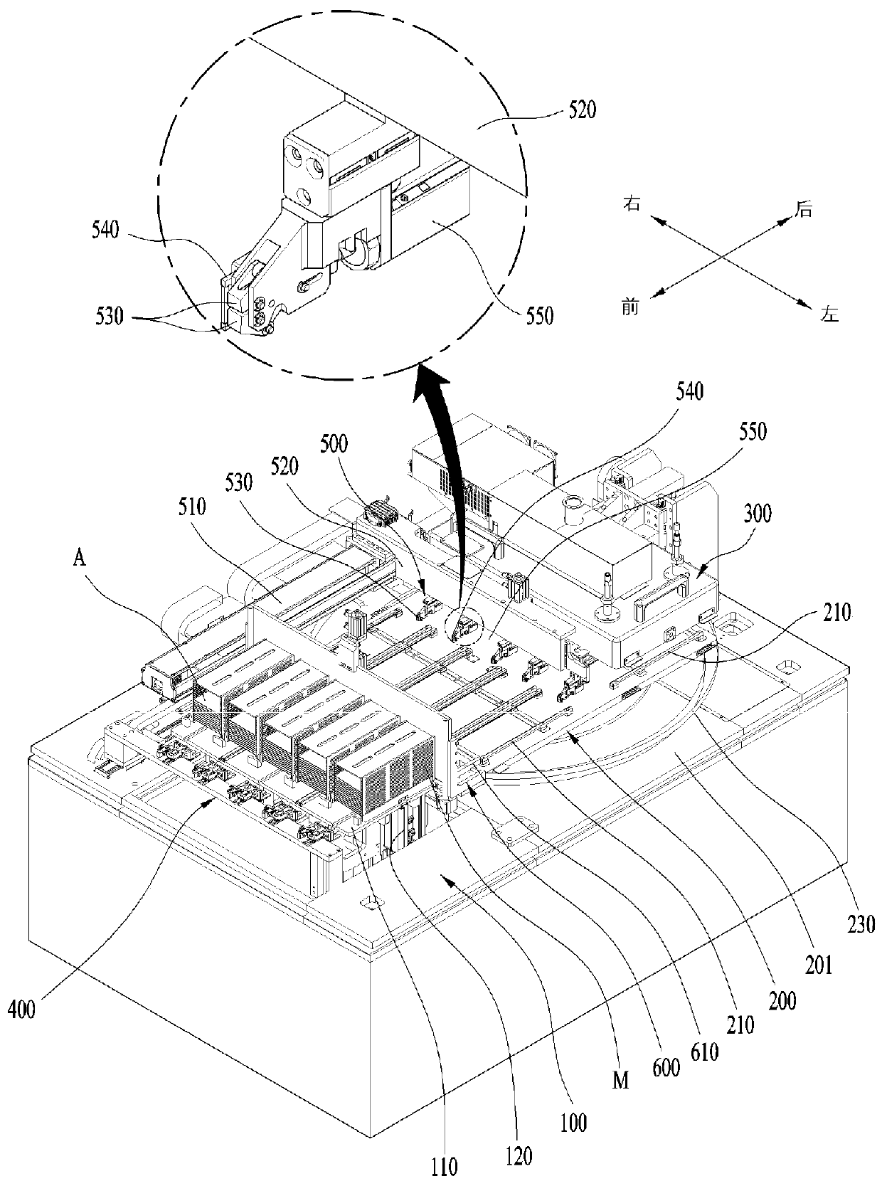
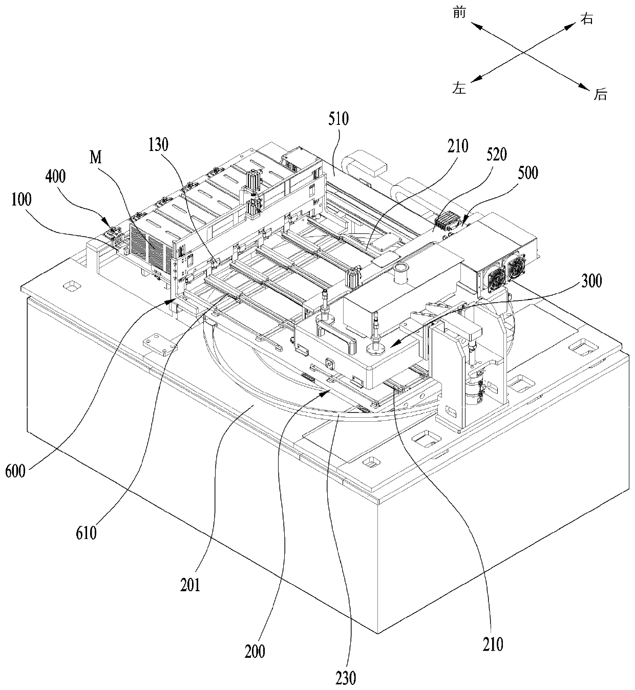
The present invention relates to a plasma cleaning apparatus for cleaning semiconductor components through plasma discharge during a semiconductor manufacturing process and, more specifically, to a semiconductor plasma cleaning apparatus for performing, in the same magazine at one place, loading of semiconductor components, which are to be cleaned, accommodated within a magazine through a rotary stage, and unloading of the cleaned semiconductor components. The present invention comprises: a magazine table (100) for lifting a magazine (M), in which a plurality of semiconductor components (A) are loaded at predetermined intervals, in steps according to a cleaning progress state; a rotary stage (200) provided at the rear of the magazine table so as to rotate in the horizontal direction; a plasma cleaning chamber (300) descending to the rotary stage so as to clean the semiconductor components supplied to the rotary stage; a first transfer member (400) located at the front of the magazine table so as to push and move, in the backward direction whenever the magazine rises in steps, the semiconductor components, which are to be cleaned, loaded inside the magazine; and a second transfer member (500) provided to rise at the upper part of the rotary stage and to move in the forward and backward directions such that the semiconductor components, which are to be cleaned, moved in the backward direction through the first transfer member are picked up, thereby supplying the semiconductor components to the rotary stage or loading the semiconductor components in the magazine, in steps, by pushing, to the magazine table, the cleaned semiconductor components located at the upper part of the rotary stage.

Description

technical field [0001] The invention relates to a plasma cleaning device used for cleaning semiconductor accessories by plasma discharge in the semiconductor manufacturing process. Specifically, the semiconductor accessories to be cleaned are loaded into the material box through a turntable, and the cleaned semiconductor accessories are unloaded in a place facing the A plasma cleaning device for semiconductors implemented in the same cartridge. Background technique [0002] Generally, the plasma cleaning device used in the semiconductor manufacturing process is a device that cleans semiconductor components such as lead frames or PCB substrates through plasma discharge, and is installed in each semiconductor manufacturing process to clean the surface of semiconductor components. [0003] That is to say, semiconductor parts go through manufacturing processes such as stripping-on-line-bonding-packaging-marking according to their types. Due to the physical and chemical treatment...

Claims


Application Information

Patent Timeline
Patent Type & Authority Patents(China)
IPC IPC(8): H01L21/302H05H1/46H01L21/677
CPCH01L21/302H01L21/677H05H1/46
Inventor 尹通燮
Owner VISIONSEMICON CO LTD
Learn More