Air-conditioner control method and device and air-conditioner

A control method and an air-conditioning technology, which are applied in the control method, device and air-conditioning field of air-conditioning, can solve the problems that the pressure of the refrigerant cannot meet the requirements of the pressure of supplementary air and increase the enthalpy, and the heat exchange efficiency between the refrigerant and the outdoor environment is reduced, and the effect of improving the performance is achieved.

Active Publication Date: 2017-06-06
QINGDAO HAIER AIR CONDITIONER GENERAL CORP LTD
6 Cites 2 Cited by

AI-Extracted Technical Summary

Problems solved by technology

[0002] For fixed-frequency or variable-frequency air conditioners currently on the market, when the air conditioner operates in summer when the outdoor temperature is too high, the enthalpy value of the refrigerant compressed by the compressor often cannot meet the enthalpy value of heat exchange, resulting in the refrigerant flowing into the condenser The heat exchange efficiency with the outdoor environment is ...

Method used

In the control method of the present invention, by adjusting the flow opening of the first throttling device with the set opening rate, the pressure change of the air outlet of the first throttling device can be made more stable, avoiding sudden increase or reduction of throttling Problems such as refrigerant turbulence caused by the opening of the flow device. Among them, the setting of the opening rate can be determined according to the difference between the initial air outlet pressure and the target air outlet pressure. Set to a larger value; similarly, when the difference is small, the opening rate is set to a smaller value.
In the control method of the present invention, by adjusting the flow opening of the second throttling device and the third throttling device with the opening rate of setting, the pressure change of the liquid outlet of the throttling device can be made more stable, avoiding sudden Problems such as refrigerant turbulence caused by increasing or decreasing the opening degree of the throttling device. Among them, the setting of the opening rate can be determined according to the difference between the initial fluid pressure and the target fluid pressure. In order to improve the rate of fluid pressure adjustment, when the difference between the initial fluid pressure and the target fluid pressure is large, The opening rate is also set to a larger value; similarly, when the difference is small, the opening rate is set to a smaller value.
In the embodiment, the control method of the present invention is first by controlling the flow opening of the second throttling device and the third throttling device on the first pipeline, so that the initial fluid pressure of the second throttling device reaches The target outlet pressure can meet the refrigerant pressure requirements for indoor heat exchange;
Optionally, the first throttling device 801 in the cooling assembly is arranged on the cooling pipeline 9 between the radiator 7 and the compressor 3, which can not only adjust the refrigerant flow rate in the cooling pipeline 9, but also It acts as an expansion valve and performs secondary throttling on the gaseous refrigerant to reduce the temperature and pressure of ...

Abstract

The invention discloses an air-conditioner control method and device and an air-conditioner, and belongs to the field of air-conditioners. The control method includes the steps of obtaining target liquid outlet pressure and initial liquid outlet pressure of a second throttling gear; adjusting the flow opening degrees of the second throttling gear and a third throttling gear to enable the liquid outlet pressure to reach the target liquid outlet pressure; obtaining target gas outlet pressure and initial gas outlet pressure of a first throttling gear, wherein the target gas outlet pressure and the initial gas outlet pressure are pressure of a refrigerant input by the first throttling gear into a compressor; and adjusting the flow opening degree of the first throttling gear to enable the initial gas outlet pressure to reach the target gas outlet pressure. According to the control method, an electronic control element is controlled to exchange heat with the gas state refrigerant flowing through a radiator, the flow opening degrees of the throttling gear can be adjusted according to the preset air supplementing temperature, and therefore the refrigerant obtained after heat exchange can meet the pressure requirement of gas replenish enthalpy increasing of the compressor, and the overall performance of the air-conditioner is promoted.

Application Domain

Mechanical apparatusSpace heating and ventilation safety systems +3

Technology Topic

EngineeringEnthalpy +1

Image

  • Air-conditioner control method and device and air-conditioner
  • Air-conditioner control method and device and air-conditioner
  • Air-conditioner control method and device and air-conditioner

Examples

  • Experimental program(1)

Example Embodiment

[0031] The following description and drawings illustrate specific embodiments of the invention sufficiently to enable those skilled in the art to practice them. Other embodiments may incorporate structural, logical, electrical, process, and other changes. The examples merely represent possible variations. Individual components and functions are optional unless explicitly required, and the order of operations may vary. Portions and features of some embodiments may be included in or substituted for those of other embodiments. The scope of embodiments of the present invention includes the full scope of the claims, and all available equivalents of the claims. Herein, various embodiments may be referred to individually or collectively by the term "invention", which is for convenience only and is not intended to automatically limit the scope of this application if in fact more than one invention is disclosed. A single invention or inventive concept. Herein, relational terms such as first and second etc. are used only to distinguish one entity or operation from another without requiring or implying any actual relationship or relationship between these entities or operations. order. Furthermore, the term "comprises", "comprises" or any other variation thereof is intended to cover a non-exclusive inclusion such that a process, method or apparatus comprising a set of elements includes not only those elements but also other elements not expressly listed elements, or also include elements inherent in such a process, method, or apparatus. Without further limitations, an element defined by the phrase "comprising a ..." does not exclude the presence of additional identical elements in the process, method or apparatus comprising said element. Various embodiments herein are described in a progressive manner, each embodiment focuses on the differences from other embodiments, and the same and similar parts of the various embodiments may be referred to each other. As for the methods, products, etc. disclosed in the examples, since they correspond to the methods disclosed in the examples, the description is relatively simple, and for relevant details, please refer to the description of the methods.
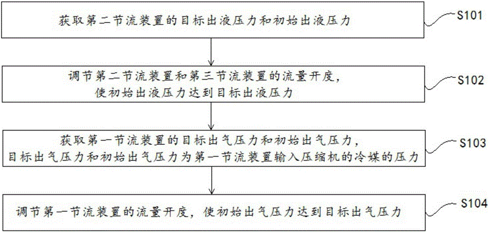
[0032] like figure 1 and figure 2As shown, the present invention provides a control method of an air conditioner, and the main steps of the control method include:
[0033] S101. Obtain the target liquid outlet pressure and the initial liquid outlet pressure of the second throttling device;
[0034] Taking the cooling mode of the air conditioner as an example, after the refrigerant flows out of the second heat exchanger of the outdoor unit, it is throttled once in the second throttling device, and then split in the flasher, in which the gaseous refrigerant flows to the first section along the cooling pipeline. The liquid refrigerant continues to flow along the first pipeline and is secondarily throttled by the third throttling device, so the pressure change of the refrigerant during the first throttling process of the second throttling device will affect To the follow-up compressor air supply enthalpy increase efficiency and indoor heat exchange efficiency, it is necessary to obtain the initial liquid pressure of the second throttling device and the target liquid pressure to make the air conditioner reach the best working state and other parameter information;
[0035] The initial liquid outlet pressure of the second throttling device can be detected by the fourth sensor arranged at the liquid outlet position of the second throttling device;
[0036] S102. Adjust the flow openings of the second throttling device and the third throttling device, so that the initial fluid outlet pressure reaches the target fluid outlet pressure;
[0037] In the embodiment, the control method of the present invention first controls the flow openings of the second throttling device and the third throttling device on the first pipeline, so that the initial fluid pressure of the second throttling device reaches the target hydraulic pressure. Force, and thus can meet the refrigerant pressure requirements of indoor heat exchange;
[0038] S103. Obtain the target air outlet pressure and the initial air outlet pressure of the first throttling device, where the target air outlet pressure and the initial air outlet pressure are the pressures of the refrigerant input into the compressor by the first throttling device;
[0039] In the embodiment, the first throttling device in the air-conditioning system is connected to the intermediate air supply port of the compressor, so the refrigerant flowing through the first throttling device plays the role of replenishing air and increasing enthalpy to the compressor, in order to ensure the compression ratio of the compressor , Improve the compression efficiency of the compressor, so the refrigerant added to the compressor needs to meet the set target outlet pressure;
[0040] The initial gas outlet pressure of the first throttling device can be detected by the third sensor installed at the gas outlet position of the first throttling device, and what is detected in the embodiment is the initial gas outlet pressure after the fluid outlet pressure reaches the target fluid outlet pressure ;
[0041] S104. Adjust the flow opening of the first throttling device, so that the initial air outlet pressure reaches the target air outlet pressure. According to the pressure parameter information of the throttling device and the compressor, the control method of the present invention controls and adjusts the flow openings of the three throttling devices, so as to simultaneously meet the indoor heat exchange requirements and the heat dissipation requirements of the electronic control components, and make it compatible with the electronic control components. The refrigerant after the heat exchange of the components can meet the pressure demand of the compressor to replenish air and increase enthalpy, so that the air conditioning system as a whole can operate in the best working state and improve its performance.
[0042] During the refrigerant circulation process, the flow adjustment among the first throttling device, the second throttling device and the third throttling device is mutually coupled, no matter which throttling device is adjusted, it will cause the rest of the throttling devices to Therefore, the core of the adjustment of the control method of the present invention is to first meet the demand of the basic air conditioner for the cooling and heat exchange of the indoor environment, and then meet the cooling components to cool the electronic control components and the compressor to supplement the air to increase the enthalpy of the refrigerant. Compared with the refrigerant flow rate required for indoor refrigeration and heat exchange, the amount of refrigerant required for cooling the cooling component and increasing the enthalpy of the compressor is less, so the way of adjusting the first throttling device in the cooling component afterward has a significant impact on the remaining throttling devices. The influence of the flow rate is relatively small, so the adjustment operation process in the embodiment is specifically to first adjust the flow openings of the second and third throttling devices to meet the basic indoor cooling requirements, and then adjust the first throttling device to meet the cooling requirements of the radiator. It is necessary that the post-adjustment of the first throttling device will cause changes in the flow rates of the second throttling device and the third throttling device, and the opening degrees of the second throttling device and the third throttling device can be fine-tuned appropriately.
[0043] In some embodiments of the present invention, the specific steps of obtaining the target fluid pressure of the second throttling device include:
[0044] Detect the evaporation pressure and condensation pressure of the air conditioner; in the embodiment, when the air conditioner operates in cooling mode, the evaporation pressure is detected by the first sensor installed at the first heat exchanger of the indoor unit, and the condensation pressure is obtained by setting the first sensor installed at the first heat exchanger of the outdoor unit. It is detected by the second sensor at the second heat exchanger;
[0045] According to the evaporating pressure and the condensation pressure, determine the target liquid outlet pressure. In the embodiment, one of the calculation formulas for the target liquid outlet pressure is:
[0046]
[0047] Among them, P 目标出液 is the target fluid pressure, P e is the evaporation pressure, P c is the condensing pressure. Through theoretical calculation, when the target liquid pressure can reach the liquid pressure corresponding to the above-mentioned evaporation pressure and condensation pressure, the cooling and heating capacity of the air conditioner system can reach the maximum efficiency. Therefore, the control method of the present invention is based on this target. The hydraulic pressure is adjusted accordingly as the target parameter.
[0048] In some embodiments of the present invention, by adjusting the flow openings of the second throttling device and the third throttling device, so that the initial fluid outlet pressure reaches the target fluid outlet pressure, the specific steps include:
[0049] When the initial fluid pressure is greater than the target fluid pressure, control the second throttling device to increase its flow opening at the first opening rate, and control the third throttling device to decrease its flow opening at the first opening rate until The initial fluid pressure reaches the target fluid pressure;
[0050] When the initial fluid pressure is less than the target fluid pressure, control the second throttling device to reduce its flow opening at the first opening rate, and control the third throttling device to increase its flow opening at the first opening rate until The initial fluid pressure reaches the target fluid pressure;
[0051] When the initial liquid outlet pressure is equal to the target liquid outlet pressure, the flow openings of the first throttling device, the second throttling device and the third throttling device are kept unchanged.
[0052] In the control method of the present invention, by adjusting the flow openings of the second throttling device and the third throttling device at a set opening rate, the pressure change of the liquid outlet of the throttling device can be made more stable, avoiding a sudden increase or decrease Problems such as refrigerant turbulence caused by the opening of the throttling device. Among them, the setting of the opening rate can be determined according to the difference between the initial fluid pressure and the target fluid pressure. In order to improve the rate of fluid pressure adjustment, when the difference between the initial fluid pressure and the target fluid pressure is large, The opening rate is also set to a larger value; similarly, when the difference is small, the opening rate is set to a smaller value.
[0053] In some embodiments of the present invention, the step of obtaining the target outlet pressure of the first throttling device includes:
[0054] Detect the suction pressure and discharge pressure of the air conditioner compressor; in the embodiment, the suction pressure and discharge pressure can be detected by the fifth sensor arranged at the compressor, and the fifth sensor has a suction port arranged on the compressor the first sensing terminal of the compressor, and the second sensing terminal arranged at the exhaust port of the compressor;
[0055] According to the suction pressure and exhaust pressure, determine the target air outlet pressure of the first throttling device; the calculation formula of the target air outlet pressure is:
[0056]
[0057] Among them, P 目标出气 is the target outlet pressure, P s is the suction pressure, P t is the discharge pressure. The embodiment of the present invention takes a two-stage compressor as an example. The pressure of the refrigerant fed into the middle air supply port is the average value of the suction pressure and the discharge pressure. When the compressor is a multi-stage compressor with three or more stages When using a compressor, the target air outlet pressure can be calculated and determined according to the specific air supply position of the air supply port.
[0058] In some embodiments of the present invention, adjusting the flow opening of the first throttling device so that the initial outlet pressure reaches the target outlet pressure includes:
[0059] When the initial air outlet pressure is greater than the target air outlet pressure, control the first throttling device to increase its flow opening at a second opening rate until the initial air outlet pressure reaches the target air outlet pressure;
[0060] When the initial air outlet pressure is less than the target air outlet pressure, control the first throttling device to reduce its flow opening at a second opening rate until the initial air outlet pressure reaches the target air outlet pressure;
[0061] When the initial air outlet pressure is equal to the target air outlet pressure, the flow opening of the first throttling device remains unchanged.
[0062] In the control method of the present invention, by adjusting the flow opening of the first throttling device at a set opening rate, the pressure change of the air outlet of the first throttling device can be made more stable, avoiding a sudden increase or decrease of the throttling device. Refrigerant turbulence and other problems caused by opening. Among them, the setting of the opening rate can be determined according to the difference between the initial air outlet pressure and the target air outlet pressure. Set to a larger value; similarly, when the difference is small, the opening rate is set to a smaller value.
[0063] The present invention also provides a control device for an air conditioner. The control device adopts the control method disclosed in the above embodiments to control the air conditioner accordingly. The device mainly includes:
[0064] The obtaining unit is used to obtain the target liquid outlet pressure and the initial liquid outlet pressure of the second throttling device; and obtain the target air outlet pressure and the initial air outlet pressure of the first throttling device, and the target air outlet pressure and the initial air outlet pressure are the The pressure of the refrigerant fed into the compressor by the device;
[0065] The main control unit is used to adjust the flow opening of the second throttling device and the third throttling device so that the initial liquid outlet pressure reaches the target liquid outlet pressure; and adjust the flow opening of the first throttling device so that the outlet pressure The target outlet pressure is reached.
[0066] In some embodiments of the present invention, the acquisition unit is also used to: acquire the evaporation pressure and condensation pressure detected by the air conditioner; determine the target fluid outlet pressure according to the evaporation pressure and condensation pressure;
[0067] The formula for calculating the target hydraulic pressure is:
[0068]
[0069] Among them, P 目标出液 is the target fluid pressure, P e is the evaporation pressure, P c is the condensing pressure.
[0070] In some embodiments of the present invention, the main control unit is used to: when the initial fluid pressure is greater than the target fluid pressure, control the second throttling device to increase its flow opening at the first opening rate, and control the third section The flow device reduces its flow opening at the first opening rate until the initial fluid pressure reaches the target fluid pressure; and when the initial fluid pressure is less than the target fluid pressure, control the second throttling device at the first opening rate Decrease its flow opening, and control the third throttling device to increase its flow opening at the first opening rate until the initial fluid pressure reaches the target fluid pressure; and when the initial fluid pressure is equal to the target fluid pressure, maintain The flow openings of the first throttling device, the second throttling device and the third throttling device remain unchanged.
[0071] In some embodiments of the present invention, the acquiring unit is used to: acquire the suction pressure and discharge pressure of the compressor detected by the air conditioner; determine the target gas outlet pressure of the first throttling device according to the suction pressure and discharge pressure ; The formula for calculating the target outlet pressure is:
[0072]
[0073] Among them, P 目标出气 is the target outlet pressure, P sis the suction pressure, P t is the exhaust pressure.
[0074] In some embodiments of the present invention, the main control unit is used to: when the initial air outlet pressure is greater than the target air outlet pressure, control the first throttling device to increase its flow opening at a second opening rate until the initial air outlet pressure reaches the target air outlet pressure; and when the initial outlet pressure is greater than the target outlet pressure, control the first throttling device to reduce its flow opening at a second opening rate until the initial outlet pressure reaches the target outlet pressure; and when the initial outlet pressure is equal to the target outlet pressure , keeping the flow opening of the first throttling device unchanged.
[0075] The air conditioning structure applied to the control method and control device in the above embodiments is as follows: image 3 As shown, the air conditioner includes an indoor unit and an outdoor unit, wherein the indoor unit includes a first heat exchanger 1 for exchanging heat with the indoor environment, and the outdoor unit includes a second heat exchanger 2 for exchanging heat with the outdoor environment. The compressor 3 that provides circulating power for the refrigerant, the computer board, single-chip microcomputer and other electrical controls are set in the outdoor unit, the first heat exchanger 1, the second heat exchanger 2 and the compressor 3 pass through the first pipeline 4 and the second pipeline The road 5 is connected to form a conventional refrigerant circulation loop. In the embodiment, when the air conditioner operates in cooling mode in summer, the refrigerant after heat exchange with the outdoor environment flows out from the second heat exchanger 2 and passes through the first pipeline 4. It flows into the first heat exchanger 1, and at the same time, the refrigerant after exchanging heat with the indoor environment flows out of the first heat exchanger 1 and flows into the second heat exchanger 2 through the second pipeline 5. Through this refrigerant circulation process, it can Realize the cooling and cooling function of the air conditioner on the indoor environment. Similarly, when operating in the heating mode in winter, the refrigerant flows between the first heat exchanger 1 and the second heat exchanger 2 in a direction opposite to that in the cooling mode. It can realize the heating and heating function of the air conditioner to the indoor environment.
[0076] In addition to the above-mentioned conventional refrigerant circulation loop, the air conditioner of the present invention also includes a cooling tube group, which is used to solve the problem of excessive temperature when the electric control is working.
[0077] Specifically, the cooling pipe group mainly includes two parts: a cooling assembly and a cooling pipeline 9, wherein the cooling assembly mainly includes:
[0078] The flasher 6, which is connected to the first pipeline 4, can evaporate part of the liquid refrigerant flowing through the first pipeline 4 into a gaseous refrigerant, and transport the gaseous refrigerant to the cooling pipeline 9, thereby utilizing The gaseous refrigerant is used as the heat exchange medium in the subsequent cooling process of the cooling pipeline 9;
[0079] The first throttling device 801 is installed on the first pipeline 4, and is used to adjust the flow rate of the gaseous refrigerant in the cooling pipeline 9, and adjust the pressure and temperature of the refrigerant after the heat exchange of the electric control, so that the inflow compression The refrigerant of machine 3 can meet the needs of compressor 3 to replenish air and increase enthalpy;
[0080] Radiator 7, the radiator 7 is connected to the cooling pipeline 9 and is arranged adjacent to the electric control. Since the electric control is mostly arranged in a semi-closed container such as an electric control box, the radiator 7 can be used as an exchange between the gaseous refrigerant and the air around the electric control. The heat carrier can control the temperature of the electric control itself below the safe working temperature by cooling the surrounding air of the electronic control component. The specific structure and type of the radiator 7 can be determined according to the structure of the outdoor unit. In the embodiment, the type of the radiator 7 provided on the cooling pipeline 9 is an advection heat exchanger, and the advection heat exchanger has the advantages of high heat transfer rate and small space occupation. Advantages, it is suitable for the structure of the outdoor unit of the air conditioner with a compact structure.
[0081] The flow sequence of the refrigerant used to dissipate heat and cool down the electric control in the cooling tube group is: first pipeline 4 → flasher 6 → radiator 7 → compressor 3, and the first throttling device 801 can be set at the flasher as required. On the cooling line 9 between the generator 6 and the compressor 3.
[0082] In the structure of supplementing air and increasing enthalpy of conventional air conditioners, the refrigerant in the refrigerant pipeline is mostly directly transported to the compressor 3. During this process, the parameters such as the temperature and pressure of the refrigerant will not change much, but in the present invention In the air conditioner, the temperature and pressure of the gaseous refrigerant flowing through the radiator 7 increase, thus reducing the subsequent compression efficiency of the compressor 3 on the refrigerant. In order to solve this problem, in one embodiment of the present invention, the air conditioner also It includes a second throttling device 802 and a third throttling device 803, wherein the second throttling device 802 is arranged on the first pipeline 4 between the second heat exchanger 2 and the flasher 6, and the third throttling device The device 803 is set on the first pipeline 4 between the first heat exchanger 1 and the flasher 6. Compared with the conventional air-conditioning structure of supplementing air and increasing enthalpy, the air conditioner is equipped with a second throttling device 802 and a third throttling device The advantage of the device 803 is that: taking the cooling mode of the air conditioner as an example, the liquid refrigerant is placed between the second heat exchanger 2 and the flasher 6 before the second heat exchanger 2 of the outdoor unit flows into the flasher 6 The second throttling device 802 can throttle the refrigerant in the first step to reduce the pressure of the refrigerant, so that the flasher 6 can evaporate the liquid refrigerant into a gas refrigerant. 7, in one embodiment of the present invention, by adjusting the opening of the first throttling device 801 and the second throttling device 802, the flow rate of the refrigerant in the cooling pipeline 9 can be adjusted, and the The temperature and pressure of the refrigerant flowing from the first throttling device 801 to the compressor 3 are lower than the temperature and pressure of the refrigerant flowing from the second heat exchanger 2 to the second throttling device 802 .
[0083] Since part of the liquid refrigerant flows into the cooling pipeline 9 in the form of gaseous refrigerant at the flasher 6, in order to ensure that the temperature and pressure of the first heat exchanger 1 flowing into the indoor unit meet the actual indoor heat exchange requirements, a The third throttling device 803 between the heater 1 and the flasher 6 can function as a throttling expansion valve for adjusting parameters such as temperature and pressure of the refrigerant flowing out of the flasher 6 .
[0084] The above-mentioned embodiment takes the cooling mode of the air conditioner operating under the high temperature condition in summer as an example. Similarly, under the low temperature condition in winter, the outdoor low temperature condition will affect the heat exchange between the outdoor unit and the outdoor environment. To ensure that the air conditioner operates in the heating mode The heating capacity at the same time, it is also necessary to perform the operation of replenishing air and increasing enthalpy on the compressor 3. When the air conditioner is running in the heating mode, the flow direction of the refrigerant in the air conditioning pipeline is opposite to that in the cooling mode. At this time, the first heat exchanger is set The third throttling device 803 between the flasher 1 and the flasher 6 can play the role of throttling of the second throttling device 802 under refrigeration conditions, and adjust the parameters such as the temperature and pressure of the refrigerant flowing into the flasher 6 in advance , while the second throttling device 802 acts as a cut-off expansion valve for adjusting parameters such as temperature and pressure of the refrigerant flowing out of the flasher 6 and flowing into the second heat exchanger 2 of the outdoor unit. In order to realize the refrigerant adjustment process under the above two working conditions, the second throttling device 802 and the third throttling device 803 adopted in the present invention are two-way throttling devices.
[0085] The outdoor unit of the air conditioner also includes a gas-liquid separator 10 for storing and delivering refrigerant to the compressor 3. The compressor 3 includes at least a primary compression part and a secondary compression part, and the primary compression part and the secondary compression part are connected to each other. There is a mixing part, wherein the primary compression part is used for primary compression of the refrigerant flowing into the gas-liquid separator 10, the mixing part is used for mixing the refrigerant flowing into the cooling pipeline 9 and the refrigerant that has been compressed through the primary stage, and the secondary compression The part is used for two-stage compression of the mixed refrigerant, so that the refrigerant output by the compressor 3 can meet the temperature and pressure required by the second heat exchanger 2 of the outdoor unit for external heat exchange.
[0086] At the same time, the air return port of the compressor 3 includes a first air return port connecting the primary compression part and the gas-liquid separator 10, and a second air return port connecting the mixing part and the radiator 7, so that the refrigerant in different refrigerant flow lines flows into Corresponding compressor 3 internal structure.
[0087] Optionally, the compressor 3 of the present invention adopts the existing intermediate air supply compressor 3, the mixing part is the intermediate air supply chamber of the intermediate air supply compressor 3, and the second air return port is the air supply chamber of the intermediate air supply compressor 3. breath.
[0088] In one embodiment of the present invention, the flasher 6 is connected in series with the first pipeline 4, and the main structure of the flasher 6 includes a liquid refrigerant part and a gas refrigerant part communicated with the liquid refrigerant part, wherein the liquid refrigerant part It has a liquid inlet and a liquid outlet connected in series with the first pipeline 4 , and a first gas outlet for the gaseous refrigerant to flow to the gaseous refrigerant part, and the gaseous refrigerant part also has a second gas outlet connected to the cooling pipeline 9 .
[0089] Correspondingly, the radiator 7 has an inlet end communicated with the second air outlet of the gas refrigerant part, and an outlet end communicated with the second air return port of the compressor 3 .
[0090] In another embodiment of the present invention, the flasher 6 is connected in parallel with the first pipeline 4, and the parallel pipeline section of the first pipeline 4 corresponding to the flasher 6 is provided with a cut-off valve, which can be controlled by controlling the first section The flow device 801 and the cut-off valve are opened or closed to conduct or block the refrigerant pipeline where the flasher 6 is located and the corresponding parallel pipeline section, for example, by opening the shut-off valve of the parallel pipeline section and closing the first throttling device 801, so that the refrigerant does not flow through the cooling pipeline 9, which is suitable for the situation where the electric control generates less heat and the temperature is kept below the safe working temperature, and is also suitable for the working condition that the compressor 3 does not need to replenish air to increase enthalpy.
[0091] At the same time, for the above-mentioned parallel connection form of the flasher 6, the amount of refrigerant flowing into the first heat exchanger 1 of the indoor unit can also be adjusted by controlling the flow opening of the first throttling device 801 and the shut-off valve and used for heat dissipation of the electric control. Or compressor 3 replenishes the amount of refrigerant to increase enthalpy, so that the air conditioner as a whole maintains an optimal working state.
[0092] Optionally, the first throttling device 801 in the cooling assembly is arranged on the cooling pipeline 9 between the radiator 7 and the compressor 3, which can not only adjust the flow rate of the refrigerant in the cooling pipeline 9, but also play an expansion role. The role of the valve is to perform secondary throttling on the gaseous refrigerant to reduce the temperature and pressure of the refrigerant, thereby improving the compression efficiency of the compressor 3 for the mixed refrigerant.
[0093] In one embodiment of the present invention, the air conditioner is provided with a first sensor for detecting indoor temperature, and the opening degrees of the first throttling device 801 and the second throttling device 802 can be adjusted according to the detected indoor temperature to meet the The amount of refrigerant required for heat exchange in the indoor environment.
[0094] like Figure 4 and Figure 5 As shown, taking the refrigeration mode as an example, the change process of the enthalpy and entropy of the refrigerant in the air-conditioning circulation process is as follows: the refrigerant at the state point A flows into the compressor 3 from the first air return port, and in the first-stage compression part After being compressed to the state point B, it flows into the mixing part. At the same time, the refrigerant in the cooling pipeline 9 is in the state point K after being throttled by the first throttling device 801, and flows into the compressor 3 from the second air return port of the compressor 3. The mixing part of the compressor 3 is mixed with the refrigerant at the state point B to become the refrigerant at the state point C, and the two-stage compression part of the compressor 3 continues to perform two-stage compression on the refrigerant, and is isentropically compressed to be the refrigerant at the state point D; The compressor 3 inputs the refrigerant at the state point D into the second heat exchanger 2, and is cooled by the outdoor environment to the liquid point E; the refrigerant enters the first pipeline 4 along the outlet of the second heat exchanger 2, and passes through the second throttling device 802 isenthalpic throttling to state point F, and then flows into the flasher 6; the refrigerant flowing out from the liquid outlet of the liquid refrigerant part of the flasher 6 is at state point G, throttling to state point I through the third flow device, After entering the first heat exchanger 1 for endothermic evaporation, it becomes the state point L, and then returns to the gas-liquid separator 10 through the second pipeline 5; at the same time, it flows out from the second gas outlet of the gaseous refrigerant part of the flasher 6 The gaseous refrigerant is at state point H, and becomes state point J after passing through the parallel flow heat exchanger and exchanging heat with the electric control. The second air return port of the machine 3 flows into the mixing part of the compressor 3.
[0095]In the above-mentioned refrigerant cycle of the present invention, in order to reduce the mutual interference effect of the two processes of electric control cooling and compressor 3 replenishment and enthalpy increase, the first throttling device 801, the second throttling device 802 and the third throttling device 802 can be controlled. The opening degree of the flow rate of the throttling device 803 is realized. For example, in the embodiment shown above, after the refrigerant flowing out of the second heat exchanger 2 of the outdoor unit is throttled by the second throttling device 802, the refrigerant is The state point E changes to F, and the process is isenthalpic throttling, the enthalpy value of the refrigerant remains unchanged, the pressure decreases, and the entropy value increases, and the temperature decreases; the refrigerant flowing through the first throttling device 801 changes from state point J to state At point K, its process is also isenthalpic throttling, the enthalpy value of the refrigerant remains unchanged, the pressure decreases, and the entropy value increases at the same time, the temperature decreases, and the efficiency of the secondary compression of the mixed refrigerant by the compressor 3 is improved; from the flasher 6 The refrigerant flowing to the third throttling device 803 changes from state point G to state point I. The process is isenthalpic throttling. The enthalpy value of the refrigerant remains unchanged and the pressure decreases. After the first heat exchanger 1 of the indoor unit, it exchanges heat with the cooling of the indoor environment.
[0096] In one embodiment of the present invention, the air conditioner is provided with a first sensor for detecting the evaporation pressure or condensation pressure of the first heat exchanger, a second sensor for detecting the evaporation pressure or condensation pressure of the second heat exchanger, and The third sensor is used to detect the outlet pressure of the first throttling device, the fourth sensor is used to detect the outlet pressure of the second throttling device, and the fifth sensor is used to detect the suction pressure and discharge pressure of the compressor. The sensor can adjust the first throttling device 801, the second throttling device 802 and the third throttling device 803 according to the detected relevant pressure parameters, so that the air conditioner can increase or decrease without affecting the indoor heat exchange efficiency. Refrigerant flow used to dissipate heat from electrical controls.
[0097] It should be understood that the present invention is not limited to the processes and structures that have been described above and shown in the accompanying drawings, and various modifications and changes can be made without departing from the scope thereof. The scope of the invention is limited only by the appended claims.

PUM

no PUM

Description & Claims & Application Information

We can also present the details of the Description, Claims and Application information to help users get a comprehensive understanding of the technical details of the patent, such as background art, summary of invention, brief description of drawings, description of embodiments, and other original content. On the other hand, users can also determine the specific scope of protection of the technology through the list of claims; as well as understand the changes in the life cycle of the technology with the presentation of the patent timeline. Login to view more.

Similar technology patents

Method and apparatus of transmitting information in wireless communication system

ActiveUS20110170489A1improve performanceeffectively transmit information
Owner:LG ELECTRONICS INC

Storage system and data processing system

InactiveUS20060031647A1avoid affect communicationimprove performance
Owner:HITACHI LTD

Classification and recommendation of technical efficacy words

Why Eureka
Try Eureka