Fan control system and method aiming at fan control signal state

A fan control and signal state technology, applied in the field of server heat dissipation, can solve problems such as low fan speed, impact on customer business, failures, etc., to avoid heat dissipation problems, ensure normal work, and improve practicability

Inactive Publication Date: 2017-06-06
ZHENGZHOU YUNHAI INFORMATION TECH CO LTD
View PDF10 Cites 2 Cited by
  • Summary
  • Abstract
  • Description
  • Claims
  • Application Information

AI Technical Summary

Problems solved by technology

For four-star servers, the backplane comparator is prone to failure during transportation due to factors such as welding and vibration. This failure is difficult to find during production, and usually occurs after a long period of use at the customer site
In practical applications, when the comparator fails, the initial output PWM signal is completely low, and the system fan will work at the lowest speed state, resulting in cooling failures such as CPU frequency reduction when the four-star server is used at the customer site, which will seri

Method used


Image

  • Fan control system and method aiming at fan control signal state
  • Fan control system and method aiming at fan control signal state
  • Fan control system and method aiming at fan control signal state

Examples


Embodiment 1

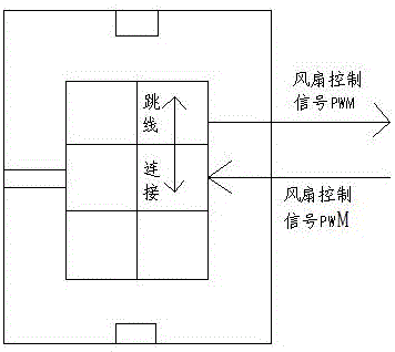
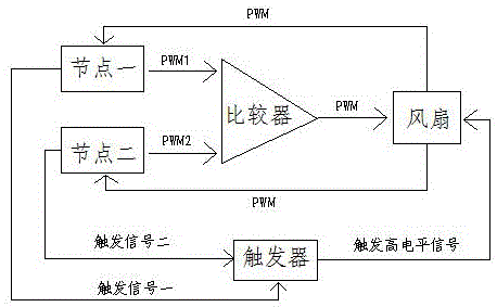
[0030] Such as figure 1 and figure 2 As shown, the fan control system for the fan control signal state of the present invention is composed of node 1, node 2, a comparator, a trigger and a fan. Node 1 and Node 2 are respectively connected to the comparator. Node 1 is used to send the PWM1 signal to the comparator, node 2 is used to send the PWM2 signal to the comparator, the comparator compares PWM1 and PWM2, and obtains a larger value as the fan control signal PWM. The fan is connected to the comparator, node 1, and node 2 respectively. Two adjacent fan control signal pins on the fan terminal pins are connected by a jumper. The internal control programs of node 1 and node 2 respectively add fan control signal recognition algorithms. The fan control signal PWM obtained by the comparator is used to control the fan, and the fan control signal PWM is sent back to node 1 and node 2. Node 1 and Node 2 judge the rationality of the fan control signal PWM through the fan control...

Embodiment 2

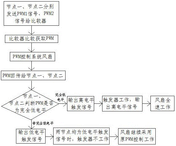
[0032] Such as image 3 As shown, in the fan control method for the fan control signal state of the present invention, nodes 1 and 2 send the PWM1 signal and PWM2 signal to the comparator, and the comparator compares the PWM1 signal and PWM2 signal to obtain a larger value as the fan control Signal PWM to control the fan. At the same time, the fan control signal PWM is sent back to node 1 and node 2. Node 1 and node 2 respectively identify the rationality of the fan control signal PWM through the internal fan control signal identification algorithm, and output trigger signal 1 and trigger signal respectively according to the judgment results. Two, send to the trigger. When it is recognized that the fan control signal PWM is completely low level, the fan control is abnormal, and at least one of the trigger signal 1 and trigger signal 2 output by node 1 and node 2 is a high level trigger signal and sent to the trigger, and the trigger works and outputs high power. Ping signal,...


PUM


Abstract

The invention discloses a fan control system and method aiming at a fan control signal state and belongs to the technical field of server heat dissipation. The fan control system aiming at the fan control signal state is composed of a first node, a second node, a comparator, a trigger and a fan. The first node and the second node are connected with the comparator, and fan control signal recognition algorithms are added to control programs in the first node and the second node respectively. The fan is connected with the comparator, the first node and the second node, and two adjacent fan control signal pins on fan terminal pins are connected. The trigger is connected with the first node, the second node and the fan. According to the fan control system aiming at the fan control signal state, after a backboard comparator breaks down, fan control can still be achieved, the problem of complete machine heat dissipation caused by component faults is avoided, therefore, normal work of a server is guaranteed, and high application and popularization value is achieved.

Description

technical field [0001] The present invention relates to the technical field of server heat dissipation, and specifically provides a fan control system and method for fan control signal states. Background technique [0002] Compared with traditional computers, servers have better scalability, ease of use, and ease of management, and are widely used by large enterprises. There are multiple nodes in the four-star server. Generally, two nodes jointly control the corresponding system fans in front. In order to avoid heat dissipation problems in the server, the PWM signals sent by the two nodes need to select the maximum value for fan control. This function is realized through the backplane comparator. Output the maximum value of the PWM signal to control the system fan. For four-star servers, the backplane comparator is prone to failure during transportation due to factors such as welding and vibration. This failure is difficult to find during production, and usually occurs afte...

Claims


Application Information

Patent Timeline
IPC IPC(8): G06F11/16G06F1/20
CPCG06F11/1608G06F1/20
Inventor 于光义
Owner ZHENGZHOU YUNHAI INFORMATION TECH CO LTD
Why Eureka
Try Eureka