PG (program guidance) signal control method and device

A signal control and signal technology, applied in the field of PG signal control methods and devices, can solve problems such as difficult timing adjustment, scattered PG signal signals, poor probability, etc., and achieve the effect of facilitating development and debugging

Inactive Publication Date: 2017-06-06
ZHENGZHOU YUNHAI INFORMATION TECH CO LTD
View PDF3 Cites 1 Cited by
  • Summary
  • Abstract
  • Description
  • Claims
  • Application Information

AI Technical Summary

Problems solved by technology

This application is very simple and convenient in a small circuit, but on a relatively large single board, too scattered PG signals will cause a lot of trouble in the later startup and debugging, especially the timing will be difficult to sort out
[0003] The PG signal of the power chip is very important in the board debugging process. However, due to the complex types of power supplies in large boards and strict timing requirements, the PG signal has problems such as signal dispersion, difficult timing adjustment, and difficult to capture when the probability is bad.

Method used


Image

  • PG (program guidance) signal control method and device
  • PG (program guidance) signal control method and device

Examples


Embodiment Construction
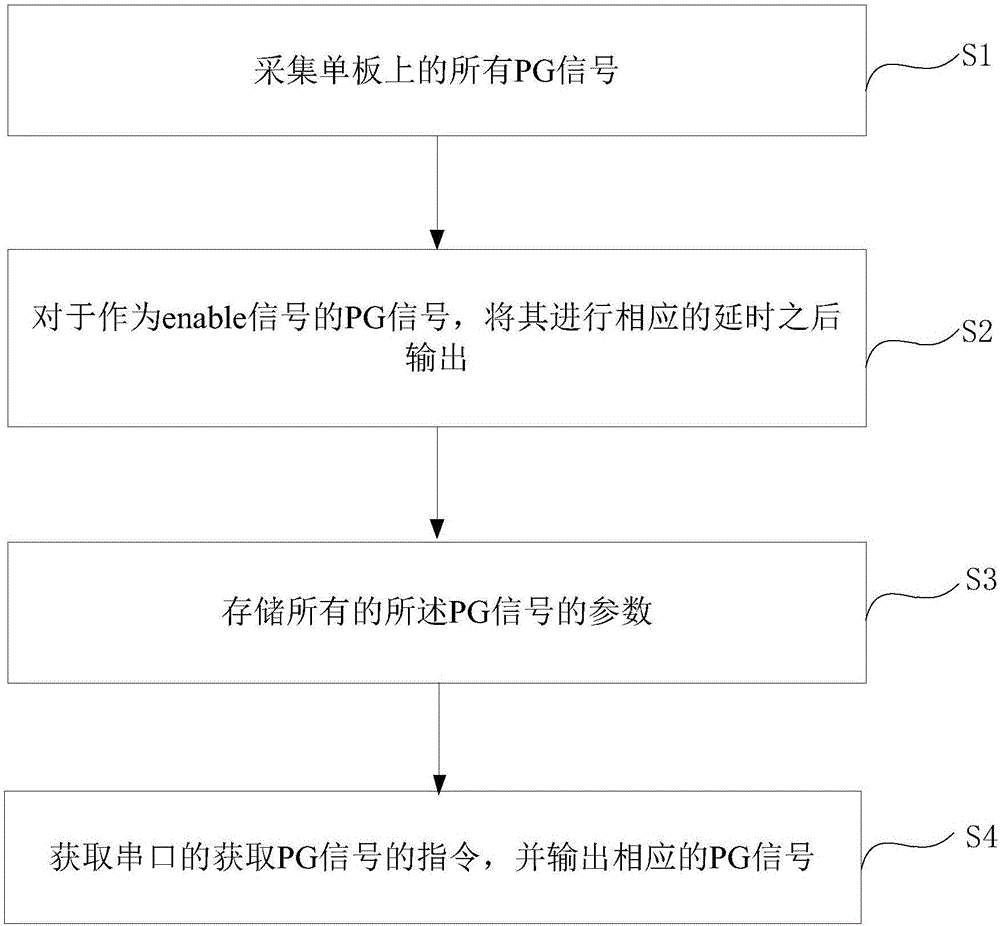
[0033] The core idea of ​​the present invention is to provide a PG signal control method and device, which can manage all PG signals on a single board in a unified manner, and store all PG signals in a module to facilitate later development and debugging.

[0034] The following will clearly and completely describe the technical solutions in the embodiments of the present invention with reference to the accompanying drawings in the embodiments of the present invention. Obviously, the described embodiments are only some, not all, embodiments of the present invention. Based on the embodiments of the present invention, all other embodiments obtained by persons of ordinary skill in the art without making creative efforts belong to the protection scope of the present invention.

[0035] The first PG signal control method provided by the embodiment of this application is as follows: figure 1 as shown, figure 1 It is a schematic diagram of the first PG signal control method provided ...


PUM


Abstract

The invention discloses a PG (program guidance) signal control method and device. The method includes the steps: acquiring all PG signals on a single plate; performing corresponding delay for the PG signals serving as enable signals, and outputting the processed PG signals; storing parameters of the all PG signals; acquiring instructions of a serial port acquiring the PG signals, and outputting corresponding PG signals. The device comprises an acquiring component, a first output component, a storage component and a second output component, the acquiring component is used for acquiring the all PG signals on the single plate, the first output component is used for performing corresponding delay for the PG signals serving as the enable signals and outputting the PG signals, the storage component is used for storing the parameters of the all PG signals, and the second output component is used for acquiring the instructions of the serial port acquiring the PG signals and outputting the corresponding PG signals. According to the method and the device, the all PG signals on the single plate can be uniformly managed and stored in a module, and later development and later debugging are facilitated.

Description

technical field [0001] The invention belongs to the technical field of power management, and in particular relates to a PG signal control method and device. Background technique [0002] In many common circuits, the power good (PG) signal generally tends to be scattered, and a single PG signal is directly used as the enable signal of the next power chip after passing through the RC delay circuit. It is very simple and convenient to apply this method in a small circuit, but on a relatively large single board, too scattered PG signals will cause a lot of trouble in the later stage of commissioning, especially in terms of timing, it will be difficult to sort out. [0003] The PG signal of the power supply chip is very important in the board debugging process. However, due to the complex types of power supplies in large boards and strict timing requirements, the PG signal has problems such as signal dispersion, difficult timing adjustment, and difficult to capture when the proba...

Claims


Application Information

Patent Timeline
Patent Type & Authority Applications(China)
IPC IPC(8): G06F13/42
CPCG06F13/4286G06F2213/0002
Inventor 王志浩
Owner ZHENGZHOU YUNHAI INFORMATION TECH CO LTD
Why Eureka
Try Eureka