A motor inverter control device and method

A control device and control method technology, applied in the direction of motor generator control, AC motor control, control of electromechanical transmission, etc., can solve the disadvantages of software development and debugging, software expansion and maintenance upgrade, software design flexibility is not high, the motor can not To meet the control requirements and other issues, to achieve the effect of flexible software design, which is conducive to software development and debugging

Active Publication Date: 2022-04-01
INVT POWER ELECTRONICS SUZHOU CO LTD
View PDF3 Cites 0 Cited by
  • Summary
  • Abstract
  • Description
  • Claims
  • Application Information

AI Technical Summary

Problems solved by technology

[0004] 1. The traditional control scheme that only uses DSP or MCU controller to control IGBT, due to the limitation of switching device, controller processing speed and resources, the highest carrier frequency can only reach 20K, low switching frequency leads to large output current harmonics, and the motor Severe heat generation, a sine wave filter needs to be configured on the output side, otherwise the temperature rise of the motor cannot meet the control requirements
And the controller is bulky, which will be limited in some applications. In addition, when the motor speed is high, the control is extremely unstable, and stable torque control cannot be obtained in high-speed and high-frequency conditions
[0005] 2. The control scheme of DSP+FPGA dual-port RAM communication is adopted. DSP is used as the man-machine interface to send and receive FPGA data through dual-port RAM. FPGA completes the high-speed and high-carrier frequency control algorithm. Control, but because the control algorithm needs to be solidified in FPGA, the flexibility of software design is not high, which is not conducive to software development and debugging, software expansion and maintenance upgrade

Method used


Image

  • A motor inverter control device and method
  • A motor inverter control device and method
  • A motor inverter control device and method

Examples


Embodiment Construction

[0034] In order to enable those skilled in the art to better understand the technical solutions in the present invention, the technical solutions in the embodiments of the present invention will be clearly and completely described below in conjunction with the drawings in the embodiments of the present invention. Obviously, the described The embodiments are only some of the embodiments of the present invention, not all of them. Based on the embodiments of the present invention, all other embodiments obtained by persons of ordinary skill in the art without making creative efforts shall fall within the protection scope of the present invention.

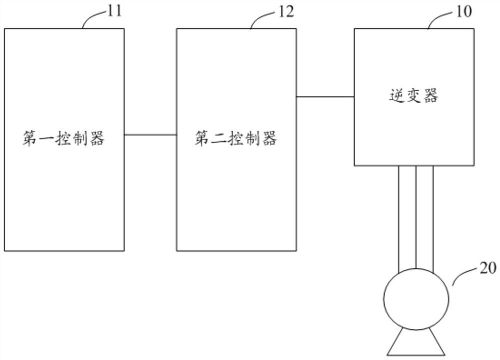
[0035] Please refer to figure 1 , figure 1 It is a schematic diagram of a motor inverter control device provided by an embodiment of the present invention. It can be seen from the figure that the motor inverter control device includes a first controller 11 and a second controller 12. The first controller 11 It is connected with the se...


PUM


Abstract

The invention discloses a motor inverter control device and method. The first controller is used to obtain a command, and when the command indicates to change the control mode of the motor inverter, it transmits to the second controller to control the motor in a preset control mode. The control algorithm program and control parameter data required for the operation of the inverter; the second controller is connected to the motor inverter to receive the control algorithm program and control parameter data transmitted by the first controller, and according to the obtained control parameters The data is used to control the motor inverter by executing the received control algorithm program, and transmit the operation data generated during the operation of the motor inverter to the first controller. The motor inverter control device and method can update the control algorithm program executed in the second controller to realize the control of the motor inverter. Compared with the prior art, the software design is more flexible, which is conducive to software development and debugging, software Expansion and maintenance upgrades.

Description

technical field [0001] The invention relates to the field of power electronics and electric drive control, in particular to a motor inverter control device and method. Background technique [0002] The traditional low-speed motors with variable frequency speed regulation have been applied in the transmission control occasions of general machinery such as fans and pumps due to their advantages of significant energy saving and convenient control. For high-speed motors (rotating speed over 10000rpm, high output frequency), which are mainly used in air conditioners or centrifugal compressors, etc., inverters that can stably and reliably drive high-speed motors are needed. The characteristics of flooding, high system efficiency and small size have been applied to a certain extent. [0003] A key issue in the high-speed motor inverter control scheme is the stable control of the current and speed of the motor when it can achieve high speed or even ultra-high speed. The current hi...

Claims


Application Information

Patent Timeline
Patent Type & Authority Patents(China)
IPC IPC(8): H02P21/00H02P27/06
CPCH02P21/0003H02P21/0021
Inventor 陈凯李忠锋刘军锋凡念
Owner INVT POWER ELECTRONICS SUZHOU CO LTD
Why Eureka
Try Eureka