Camera calibration method and device for visual navigation unmanned aerial vehicle

A camera calibration and visual navigation technology, applied in image analysis, image data processing, instruments, etc., can solve the problems of complex implementation process and low precision, and achieve the effect of avoiding the selection process, simplifying the operation process, and reducing the complexity of the algorithm

Active Publication Date: 2017-06-06
CHENGDU TOPPLUSVISION TECH CO LTD
View PDF8 Cites 37 Cited by
  • Summary
  • Abstract
  • Description
  • Claims
  • Application Information

AI Technical Summary

Problems solved by technology

[0004] The purpose of the present invention is to provide a camera calibration method and device for visual navigation d...

Method used


Image

  • Camera calibration method and device for visual navigation unmanned aerial vehicle
  • Camera calibration method and device for visual navigation unmanned aerial vehicle
  • Camera calibration method and device for visual navigation unmanned aerial vehicle

Examples


Embodiment Construction

[0040] In order to enable those skilled in the art to better understand the solution of the present invention, the present invention will be further described in detail below in conjunction with the accompanying drawings and specific embodiments. Apparently, the described embodiments are only some of the embodiments of the present invention, but not all of them. Based on the embodiments of the present invention, all other embodiments obtained by persons of ordinary skill in the art without making creative efforts belong to the protection scope of the present invention.

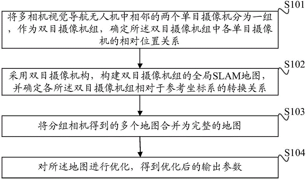
[0041] A flow chart of a specific embodiment of the camera calibration method of the visual navigation drone provided by the present invention is as follows figure 1 As shown, the method includes:

[0042] Step S101: Divide two adjacent monocular cameras in the multi-camera visual navigation drone into a group as a binocular camera group, and determine the relative positional relationship of each monocular ca...


PUM


Abstract

The invention discloses a camera calibration method and device for a visual navigation unmanned aerial vehicle (UAV). The method comprises steps of: grouping two adjacent monocular cameras in a multi-camera visual navigation UAV as a binocular camera group, and determining the relative position relation of respective monocular cameras in the binocular camera group; constructing a global SLAM map of the binocular camera group by using a binocular camera mechanism and determining the conversion relation of each binocular camera group relative to a reference coordinate system; merging maps obtained by the grouped cameras into a complete map; and optimizing the map to obtain an optimized output parameter. The method and the device are simple and easy to implement, and avoid a complex calibration block selection process. A continuous global map established in the calibration process can be used for the visual positioning and navigation of the UAV, reduces algorithm complexity of system real-time computing, and simplifies the operation procedure of a traditional calibration method.

Description

technical field [0001] The invention relates to the technical field of machine vision, in particular to a camera calibration method and device for a visual navigation drone. Background technique [0002] The UAV based on multi-camera visual navigation is a kind of miniature flying robot that uses visual navigation. It has many advantages such as flexible flight, hoverability, and wide field of vision, and has good application and research value. Compared with monocular, the use of multi-eye stereo vision camera can reduce the constraint problem of monocular camera path planning, can extract more image features, and can measure scale at the same time. Since the navigation and speed calculation of the UAV depend on its accurate positioning and map information, it is necessary to study the calibration and positioning composition methods of the UAV vision system. [0003] Traditional multi-camera UAV vision cameras use methods such as checkerboard calibration blocks for visual ...

Claims


Application Information

Patent Timeline
IPC IPC(8): G06T7/80
Inventor 罗元泰吕传龙周剑张小苗
Owner CHENGDU TOPPLUSVISION TECH CO LTD
Why Eureka
Try Eureka