Crushing assembly and crusher comprising same

A crusher and component technology, which is applied in the direction of grain processing, etc., can solve the problems of reducing production efficiency, tool edge wear, and reducing production efficiency, so as to achieve the effects of reducing pretreatment processes, saving production costs, and improving production efficiency

Active Publication Date: 2017-06-09
GREE ELECTRIC APPLIANCES INC OF ZHUHAI
12 Cites 15 Cited by

AI-Extracted Technical Summary

Problems solved by technology

One is the blade-cutting crusher, the blade is fixed on the main shaft and the body, and the plastic is cut through the operation of the main shaft. This type of equipment is low in price and is mainly used for crushing pure plastics such as beverage bottles, and for crushing belts such as TV sets. Home appliance shells with metal such as screws are likely to cause wear on the cutting edge and red...

Method used

[0027] The crushing assembly 110, the first cutter 111 rotates under the drive of the rotating shaft 113 to shred materials such as plastic shells, and the second cutter 112 that swings relative to the rotating shaft 113 smashes the materials. The combination of the first cutter 111 and the second cutter 112 reduces the wear of the cutter, realizes the rapid crushing of complex plastics with metal impurities such as screws, reduces the metal separation pretreatment process, saves production costs, and improves production efficiency. Productivity.
[0028] Referring to FIG. 2, in one embodiment, in the axial direction of the rotating shaft 113, a plurality of first cutters 111 and a plurality of second cutters 112 are arranged alternately and at intervals. The first cutter 111 and the second cutter 112 are arranged in a staggered manner, which can further improve the crushing efficiency.
[0029] Referring to FIG. 3, in one embodiment, in the circumferential di...

Abstract

The invention relates to a crushing assembly. The crushing assembly comprises a first tool, a second tool and a rotary shaft. The first tool and the second tool are arranged on the rotary shaft. The first tool is fixed relative to the rotary shaft. The second tool can swing relative to the rotary shaft. According to the crushing assembly, the first tool is driven to rotate by the rotary shaft so that a plastic shell and other materials can be shredded, and the materials are broken into pieces by the second tool swinging relative to the rotary shaft. By adopting the mode that the first tool and the second tool are combined, tool abrasion is reduced, quick crushing of complex plastic containing screws and other metal impurities is achieved, the metal separation pretreatment procedure is omitted, the production cost is reduced, and the production efficiency is improved. The invention further relates to a crusher comprising the crushing assembly.

Application Domain

Technology Topic

Metal impuritiesCrusher

Image

  • Crushing assembly and crusher comprising same
  • Crushing assembly and crusher comprising same
  • Crushing assembly and crusher comprising same

Examples

  • Experimental program(1)

Example Embodiment

[0024] In order to facilitate the understanding of the present invention, the present invention will be described more fully below with reference to the associated drawings. Preferred embodiments of the invention are shown in the accompanying drawings. However, the present invention can be embodied in many different forms and is not limited to the embodiments described herein. On the contrary, these embodiments are provided to make the understanding of the disclosure of the present invention more thorough and comprehensive.
[0025] It should be noted that when an element is referred to as being “fixed” to another element, it can be directly on the other element or there can also be an intervening element. When an element is referred to as being "connected to" another element, it can be directly connected to the other element or intervening elements may also be present. The terms "vertical," "horizontal," "left," "right," and similar expressions are used herein for purposes of illustration only.
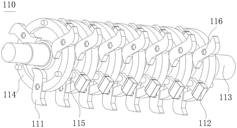
[0026] refer to figure 1 , the crushing assembly 110 in one embodiment includes a first cutter 111 , a second cutter 112 and a rotating shaft 113 . The first cutter 111 and the second cutter 112 are arranged on the rotation shaft 113 , the first cutter 111 is fixed relative to the rotation shaft 113 , and the second cutter 112 is swingable relative to the rotation shaft 113 .
[0027] In the crushing assembly 110, the first cutter 111 rotates under the drive of the rotating shaft 113 to shred materials such as plastic casings, and the second cutter 112 swings relative to the rotating shaft 113 to crush the materials. The combination of the first cutter 111 and the second cutter 112 reduces the wear of the cutter, realizes the rapid crushing of complex plastics with metal impurities such as screws, reduces the metal separation pretreatment process, saves production costs, and improves production efficiency. Productivity.
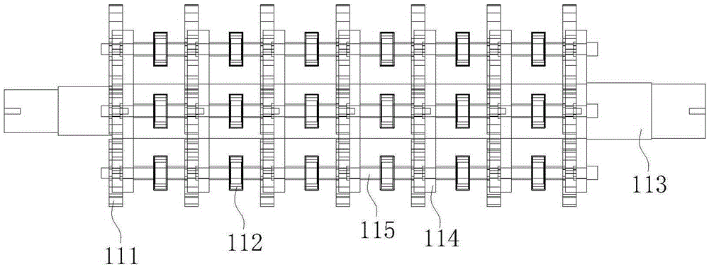
[0028] refer to figure 2 , in one embodiment, in the axial direction of the rotating shaft 113, a plurality of first cutters 111 and a plurality of second cutters 112 are arranged alternately and at intervals. The first cutter 111 and the second cutter 112 are arranged in a staggered manner, which can further improve the crushing efficiency.
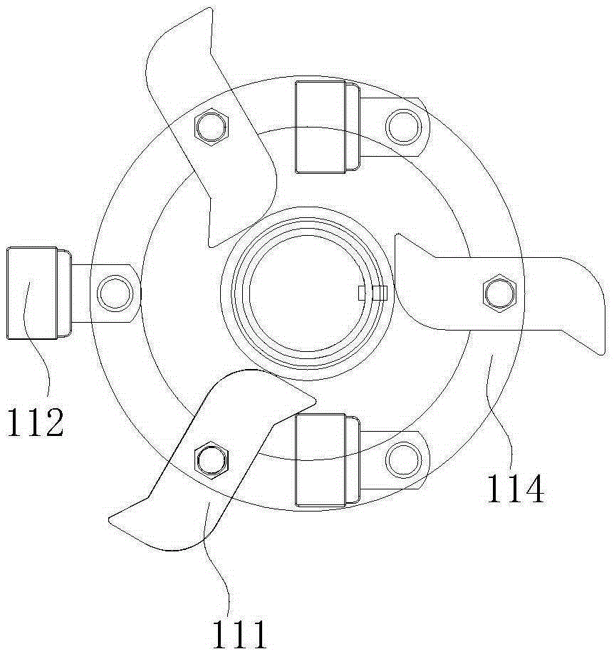
[0029] refer to image 3 , in one embodiment, in the circumferential direction of the rotating shaft 113, a plurality of first cutters 111 and a plurality of second cutters 112 are arranged alternately and at intervals. The first cutter 111 and the second cutter 112 are arranged in a staggered manner, which can further improve the crushing efficiency.
[0030] Continue to refer to figure 1 Specifically, the first cutter 111 is a hook cutter, and the second cutter 112 is a hammer cutter. The radial extension length of the first cutter 111 on the rotation axis 113 is greater than the radial extension length of the second cutter 112 on the rotation axis 113 . When the crushing unit 110 works in this way, the first cutter 111 firstly shreds the material, and the second cutter 112 then breaks the initially shredded material fragments with screws and other metals into smaller particles, further reducing the metal impurities The damage of the material to the cutter is reduced, and the production efficiency of the crushing assembly 110 is improved.
[0031] Specifically, the end of the first cutter 111 is provided with a hook protruding toward one side. More specifically, the hooks are provided at both ends of the first knife 111 .
[0032] Specifically, the end of the second cutter 112 is provided with a rectangular parallelepiped hammer. It can be understood that the hammer portion of the second cutter 112 can also be set in other shapes such as a sphere.
[0033] In one embodiment, the crushing assembly further includes a cutter head 114 , the cutter head 114 is fixed on the rotating shaft 113 , and a plurality of first knives 111 are arranged on the cutter head 114 along the radial direction of the cutter head 114 .
[0034] Specifically, there are multiple cutter heads 114 , and the plurality of cutter heads 114 are sheathed on the rotating shaft 113 at intervals in the axial direction.
[0035] In one embodiment, the crushing assembly 100 further includes a support shaft 115 connected to the cutter head 114 , the second cutter 112 is rotatably connected to the support shaft 115 , so that the second cutter 112 can swing relative to the rotation shaft 113 .
[0036] Specifically, the axis of the support shaft 115 is parallel to the axis of the rotating shaft 113 .
[0037] Specifically, the support shaft 115 is sequentially connected to a plurality of cutter heads 114 , and the second cutter 112 is disposed on the support shaft 115 and located between two adjacent cutter heads 114 .
[0038] Specifically, the end of the second cutter 112 may be exposed to the cutter head 114 when facing outward. It can be understood that, since the second cutter 112 is rotatably connected to the support shaft 115, when the crushing assembly 110 is not working, the end of the second cutter 112 faces vertically downward due to gravity. When the crushing assembly 110 is working, the second cutter 112 is subjected to the centrifugal force of the rotating shaft 113 , and the end of the second cutter 112 is exposed to the cutter head 114 , so that the second cutter 112 acts on the material.
[0039] Specifically, each cutter head 114 is provided with a plurality of first knives 111 , and the support shaft 115 is connected to the interval between two adjacent first knives 111 of the cutter head 114 connected thereto. Specifically, the multiple first cutters 111 of each cutter head 114 are evenly arranged in the circumferential direction. The support shaft 115 is evenly connected to the spaced position between two adjacent first cutters 111 of the cutter head 114 connected thereto.
[0040] Specifically, the first cutters 111 of the plurality of cutter heads 114 are provided correspondingly.
[0041] Specifically, in this embodiment, each cutter head 114 is provided with three first cutters 111 , and three support shafts 115 are sequentially connected to a plurality of cutter heads 114 .
[0042] Specifically, the second tool 112 is relatively fixedly connected to the support shaft 115 in the axial direction.
[0043]Specifically, the cutter head 114 is fixed relative to the rotating shaft 113 . Specifically, the cutter head 114 is keyed to the rotating shaft 113 . Specifically, in this embodiment, the cutter head 114 is provided with a sleeve, and the sleeve is connected to the rotating shaft 113 through a key. Specifically, the crusher 100 further includes a bolt 116 through which the first cutter 111 is fixed on the cutter head 114 .
[0044] refer to Figure 4 , the present invention also provides a crusher 100 according to an embodiment, including a crushing assembly 110 .
[0045] In the crushing assembly 110 of the above-mentioned crusher 100 , the first cutter 111 rotates under the drive of the rotating shaft 113 to shred materials such as plastic casings, and the second cutter 112 swings relative to the rotating shaft 113 to crush the materials. The combination of the first cutter 111 and the second cutter 112 reduces the wear of the cutter, realizes the rapid crushing of complex plastics with metal impurities such as screws, reduces the metal separation pretreatment process, saves production costs, and improves production efficiency. Productivity. Specifically, using the crusher 100 above, the crushing efficiency can be increased by more than 80%.
[0046] In one of the embodiments, the crusher 100 further includes a machine body 120 and a driving mechanism 130 . The machine body 120 is provided with a material inlet 121 and a material outlet 122. The inside of the machine body 120 is provided with a crushing chamber 123. The crushing assembly 110 is arranged in the crushing chamber 123 and the driving mechanism 130 is connected to the rotating shaft 113. The crushing chamber 123 is connected to the feeding material. The port 121 and the discharge port 122 are connected respectively.
[0047] Specifically, in this embodiment, the driving mechanism 130 is a motor. More specifically, the crusher 100 further includes a transmission belt 140 , and the driving mechanism 130 is connected to the rotating shaft 113 through the transmission belt 140 .
[0048] In one of the embodiments, the body 120 is further provided with a feed chamber 124 , and the feed port 121 communicates with the crushing chamber 123 through the feed chamber 124 .
[0049] Specifically, a plurality of baffle plates 1240 are arranged in the feeding chamber 124, and along the direction of the material from the feeding chamber 124 to the crushing chamber 123, a plurality of baffle plates 1240 are arranged at intervals on the inner wall of the feeding chamber 124 and are adjacent to each other. The two baffles 1240 are disposed on opposite inner walls of the feeding cavity 124 . The two adjacent material baffles 1240 refer to the two adjacent material baffles 1240 in the direction from the feeding chamber 124 to the crushing chamber 123 . In this way, the material enters the feeding chamber 124 from the feeding port 121, and the material enters the crushing chamber 123 sequentially through the action of the baffle plate 1240, so as to prevent the material from accumulating and hanging in the feeding chamber 124, causing the crushing assembly 110 to be unable to cut the idling phenomenon of the material. Increase energy consumption.
[0050] Specifically, one end of the baffle plate 1240 is fixedly connected to the feed chamber 124, and the other end of the baffle plate 1240 extends into the feed chamber 124 and is set toward the crushing chamber 123, so that the material can slide down from the material baffle 1240 better. To the crushing chamber 123. In one of the embodiments, the crusher 100 further includes an automatic temperature control device 150 , and the automatic temperature control device 150 is used to adjust the temperature in the crushing cavity 123 . After the crusher 100 works for a period of time, the temperature in the crushing cavity 123 is too high to make the crusher 100 unable to continue working. Therefore, the automatic temperature control device 150 is used to adjust the temperature in the crushing cavity 123 to ensure the normal operation of the crusher 100.
[0051] Specifically, the automatic temperature control device 150 includes a temperature control device 151 and a spray device 152 , the temperature control device 151 is used to control the opening or closing of the spray device 152 , and the spray device 152 is used to cool the crushing chamber 123 . When the temperature in the crushing chamber 123 is too high, the temperature control device 151 controls the spray device 152 to start to cool down the crushing chamber 123 . More specifically, the automatic temperature control device 150 may also include a temperature sensing device (not shown) capable of monitoring the temperature in the crushing chamber 123 in real time. It can be understood that the spraying device 152 can release a cooling medium, which is sprayed into the crushing cavity 123 to reduce the temperature.
[0052] More specifically, the spray device 152 is provided with a spray port 1520 , and the spray port 1520 is connected to the top of the crushing chamber 123 .
[0053] In one embodiment, the crusher 100 further includes a screen 160 disposed in the crushing cavity 123 and below the crushing assembly 110 . The material crushed by the crushing assembly 110 passes through the screen 160 to obtain particles of a suitable size for recycling and reuse.
[0054] In one of the embodiments, the crusher 100 also includes a dust removal port 171, a dust removal pipe 172 and a dust collector 173, the dust removal port 171 communicates with the crushing chamber 123, and the two ends of the dust removal pipe 172 communicate with the dust removal port 171 and the dust collector respectively. 173. The dust collector 173 can remove the dust generated in the crusher 100 in time, and reduce the influence of the dust on the working efficiency of the crusher 100 . Specifically, the dust removal port 171 is located below the screen 160 .
[0055] In one of the embodiments, the crusher 100 further includes a frame 180 on which the machine body 120 and the driving mechanism 130 are both arranged.
[0056] The various technical features of the above-mentioned embodiments can be combined arbitrarily. To make the description concise, all possible combinations of the various technical features in the above-mentioned embodiments are not described. However, as long as there is no contradiction in the combination of these technical features, should be considered as within the scope of this specification.
[0057] The above-mentioned embodiments only express several implementation modes of the present invention, and the descriptions thereof are relatively specific and detailed, but should not be construed as limiting the patent scope of the invention. It should be pointed out that those skilled in the art can make several modifications and improvements without departing from the concept of the present invention, and these all belong to the protection scope of the present invention. Therefore, the protection scope of the patent for the present invention should be based on the appended claims.

PUM

no PUM

Description & Claims & Application Information

We can also present the details of the Description, Claims and Application information to help users get a comprehensive understanding of the technical details of the patent, such as background art, summary of invention, brief description of drawings, description of embodiments, and other original content. On the other hand, users can also determine the specific scope of protection of the technology through the list of claims; as well as understand the changes in the life cycle of the technology with the presentation of the patent timeline. Login to view more.

Similar technology patents

Low friction chain

ActiveUS20080020882A1Reduce wearCombustion efficiency be improveDriving chainsEdge surfaceLow friction
Owner:TSUBAKIMOTO CHAIN CO

Insulator cleaning robot

Owner:STATE GRID INTELLIGENCE TECH CO LTD

Classification and recommendation of technical efficacy words

Why Eureka
Try Eureka