Steel tube cutting device

A steel pipe and sawing technology, applied in sawing machine devices, metal sawing equipment, metal processing equipment, etc., can solve the problems of inconvenient storage and transportation, burrs, etc., and achieve the effect of convenient storage and transportation

Inactive Publication Date: 2017-06-09
长葛市圆方不锈钢制品有限公司
View PDF8 Cites 5 Cited by
  • Summary
  • Abstract
  • Description
  • Claims
  • Application Information

AI Technical Summary

Problems solved by technology

[0002] The steel pipe cutting device has a workbench, on which a pole is arranged, and a power-linked saw blade is installed on the pole, and on the workbench, there is a clamping part for clamping the steel pipe. Steel pipe, when the saw blade is running, the steel pipe can be cut; in the prior art, there is no rotating part on the clamping part, that is to say, the steel pipe is not moving during the cutting process of the steel pipe, so the cut steel pipe There will be burrs on the outside of one side of the cut, which brings inconvenience to storage and transportation

Method used


Image

  • Steel tube cutting device
  • Steel tube cutting device

Examples


Embodiment Construction

[0015] The present invention will be further described below in conjunction with the accompanying drawings.

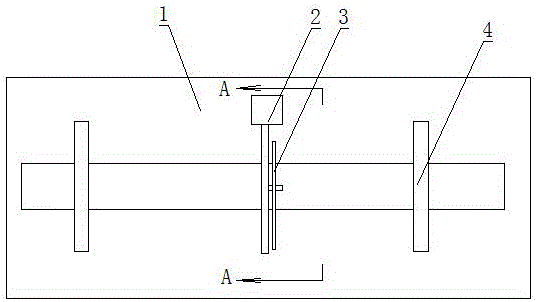
[0016] Such as figure 1 As shown, a steel pipe cutting device includes a workbench 1, on which a vertical pole 2 is arranged, and a power-linked saw blade 3 is installed on the pole, and on the workbench, there is also a device for clamping a steel pipe 4. Clamping part 5, the clamping part clamps the steel pipe, when the saw blade is running, it can cut the steel pipe, its features are:

[0017] There is a slideway 6 on the workbench, the clamping part 5 is installed on the slideway, and the cylinder 7 is connected to the clamping part, the cylinder shrinks, and the clamping part runs so that the steel pipe runs to the sawing station;

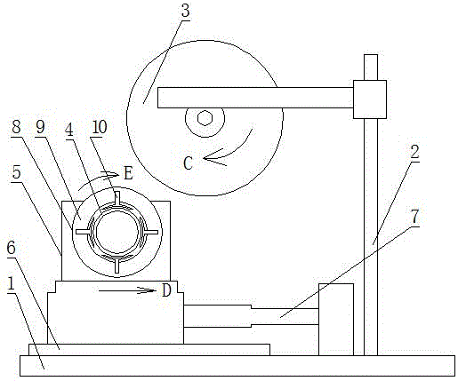
[0018] The clamping part has a clip 8 for clamping the steel pipe, and the power device is linked with the clip. When the power device runs, the clip can rotate the sawed steel pipe.

[0019] Such as figure 2 As shown, C is the dir...


PUM


Abstract

The invention relates to equipment in the technical field of tube stock production, and is named after a steel tube cutting device. The steel tube cutting device comprises a workbench, wherein a vertical pole is arranged on the workbench; a dynamically linked saw web is further mounted on the vertical pole; a clamping component for clamping a steel tube is further arranged on the workbench; the steel tube is clamped by the clamping component; and when the saw web operates, the steel tube can be cut. The steel tube cutting device is characterized in that a slideway is arranged on the workbench, the clamping component is mounted on the slideway, a cylinder is further connected with the clamping component, and the shrinkage of the cylinder and the operation of the clamping component enable the steel tube to be operated at a saw cutting station; the clamping component is provided with a clamping piece for clamping the steel tube, a power device is further linked with the clamping piece, the power device operates, and the clamping piece can enable the saw-cut steel tube to rotate. According to the steel tube cutting device, no burrs can exist on the periphery at the position of the notch of the cut steel tube, and the burrs are all inside the notch, so that steel tubes are convenient to store and transport.

Description

technical field [0001] The invention relates to equipment in the technical field of pipe material production, in particular to a steel pipe cutting device. Background technique [0002] The steel pipe cutting device has a workbench, on which a pole is arranged, and a power-linked saw blade is installed on the pole, and on the workbench, there is a clamping part for clamping the steel pipe. Steel pipe, when the saw blade is running, the steel pipe can be cut; in the prior art, there is no rotating part on the clamping part, that is to say, the steel pipe is not moving during the cutting process of the steel pipe, so the cut steel pipe There will be burrs on the outside of one side of the cut, which brings inconvenience to storage and transportation. Contents of the invention [0003] The object of the present invention is to address the above disadvantages and provide a steel pipe cutting device that has no burrs on the outer periphery of the cut and is convenient for stor...

Claims


Application Information

Patent Timeline
Patent Type & Authority Applications(China)
IPC IPC(8): B23D45/12B23D45/02B23D47/04
CPCB23D45/124B23D45/02B23D47/047
Inventor 尚依铂秦二伟黄永国
Owner 长葛市圆方不锈钢制品有限公司
Why Eureka
Try Eureka