Active positioning door rolling machine

A rolling door machine, active technology, applied in the direction of windows/doors, door/window protection devices, building components, etc., can solve the problems of large space occupation, inconvenient disassembly and assembly, complicated installation, etc., to achieve good rigidity, convenient installation, Sophisticated look

Inactive Publication Date: 2017-06-09
漳州市亿锦进出口有限公司
View PDF5 Cites 1 Cited by
  • Summary
  • Abstract
  • Description
  • Claims
  • Application Information

AI Technical Summary

Problems solved by technology

When the electromagnetic coil is burned, short circuited or the brake disc nut falls off and gets stuck, the door curtain will hover at the current position at the same time. Due to the inconvenient disassembly and assembly, the problem can only be solved by destructive removal, so it is easy to seriously damage the door curtain or other components. , resulting in a lot of waste
[0003] In addition, when the motor is broken, blocked or the electric transmission mechanism is broken, the system will be stuck
[0004] Furthermore, the traditional motor must have a bracket plate, a transmission chain, a ratchet, etc. for transmission; the installation is complicated, cumbersome, time-consuming, manpower and material resources, etc.; it takes up a lot of space and is not convenient for boxes, etc.
[0005] Finally, the traditional support plate must be fixed by electric welding machine, angle iron and other tools, and the actual working conditions are harsh

Method used


Image

  • Active positioning door rolling machine
  • Active positioning door rolling machine
  • Active positioning door rolling machine

Examples


Embodiment 1

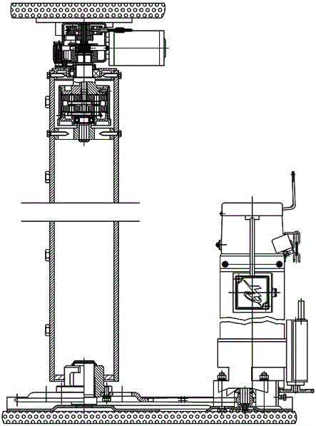
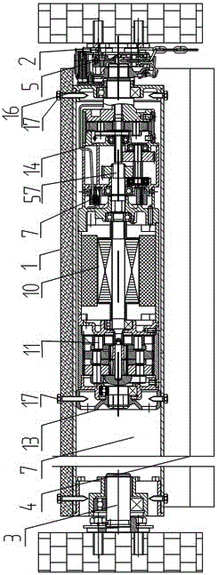
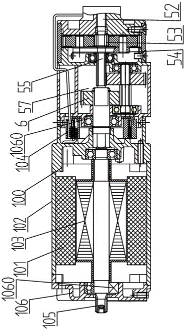
[0035] figure 1 , 2 , a kind of active positioning rolling door machine shown in 3, it comprises: reel assembly, main support 2 and attached support 3; Described reel assembly is provided with motor 10, electric gearbox 11, and fixedly winds a Roller blind 4; the output shaft of the motor 10 is connected to the driving wheel 13 through the electric gearbox 11, the driving wheel 13 is rotatably fixed on the attached support 3, and the reel assembly is fixedly sleeved on the driving wheel 13 , so that one end of the reel assembly can be rotatably fixed on the attached support 3; the other end of the motor 10 is connected to a ratchet 15 through a manual gearbox 14, and the ratchet 15 is rotatably fixed on the main support 2, so that the reel The other end of the assembly is rotatably fixed on the main support 2 through a ratchet 15; the reel assembly or the main support 2 is provided with a normally closed clutch mechanism 5 of the ratchet 15, so that when the normally closed ...

Embodiment 2

[0045] Such as Figure 5 An active positioning rolling door machine is shown, which includes: a reel assembly, a main support and an attached support; the reel assembly is provided with a motor 20, an electric gearbox 21, and a roller blind is fixedly wound; The output shaft of the motor 20 is connected to the driving wheel 22 through the electric gearbox 21, the driving wheel 22 is rotatably fixed on the attached support, and the reel is fixedly sleeved on the driving wheel 22, so that one end of the reel assembly can rotate fixed on the attached support; the other end of the motor 20 is connected to a rocker output end 24 through a manual gearbox 23, and the rocker 25 is fixed on the main support; on the reel assembly or the main support There is a normally closed clutch mechanism of the manual gearbox 23, so that when the normally closed clutch mechanism is in the open state, the output end of the manual gearbox 23 can rotate relative to the main support; when the normally ...

Embodiment 3

[0048] As described in Embodiments 1 and 2, mechanisms such as an active positioning rolling door machine and an emergency gearbox can also be located at the other end of the motor, and the specific scheme is as follows:

[0049] A motor and a driving wheel are arranged in the reel assembly, and the power output end of the motor drives and connects a common gearbox, and the driving wheel drives and connects the reel assembly; the driving wheel is provided with a normally open clutch, and through the normally open clutch Connect the output end of the common gearbox and the output end of the emergency gearbox respectively. When the normally open clutch is in the open state, the driving wheel and the output end of the common gearbox rotate synchronously and can rotate relative to the output end of the emergency gearbox. When the open clutch is in the closed state, the drive wheel can rotate relative to the output end of the common gearbox and rotate synchronously with the output e...


PUM


Abstract

The invention provides an active positioning door rolling machine. The machine comprises a reel assembly and two supports, wherein the two ends of the reel assembly are arranged on the two supports respectively. The reel assembly is internally provided with one or more non-rotating parts, and the non-rotating parts are fixedly arranged on one of the supports, so that the non-rotating parts do not rotate relative to the supports; the machine is characterized in that a normally closed clutch mechanism is arranged between one fixedly arranged support and one non-rotating part, when the normally closed clutch mechanism is in an open state, the non-rotating parts can rotate relative to the fixedly arranged support, and an inner power system of the reel assembly does not motivationally drive a reel any more. When a motor and a gearbox or other power parts or transmission components within the reel assembly can not work normally, the normally closed clutch mechanism can be opened, an emergency power mechanism or an external power mechanism drives the reel assembly to rotate, a door curtain is then driven to move up and down at any time, and the problem that traditional similar products need to be dissembled with explosive force is solved.

Description

technical field [0001] The invention relates to a door rolling machine, in particular to a braking mechanism of the door rolling machine. Background technique [0002] Both traditional rolling gate motors and tubular motors must use the principle of pulling in and out of electromagnets to perform axial braking. When the electromagnetic coil is burned, short circuited or the brake disc nut falls off and gets stuck, the door curtain will hover at the current position at the same time. Due to the inconvenient disassembly and assembly, the problem can only be solved by destructive removal, so it is easy to seriously damage the door curtain or other components. , resulting in a lot of waste. [0003] In addition, when the motor is broken, blocked or the electric transmission mechanism is broken, the system will be stuck. [0004] Furthermore, the traditional motor must have a bracket plate, a transmission chain, a ratchet, etc. for transmission; the installation is complicated,...

Claims


Application Information

Patent Timeline
Patent Type & Authority Applications(China)
IPC IPC(8): E06B9/74
CPCE06B9/74
Inventor 不公告发明人
Owner 漳州市亿锦进出口有限公司
Why Eureka
Try Eureka