
Dragging, pedaling and recoil force integrated bicycle

A bicycle and recoil technology, which is applied to vehicle parts, transportation and packaging, and rider driving, etc., can solve problems such as discomfort, difficulty in manufacturing, and inability to fully display human body energy

Active Publication Date: 2013-04-17
耿康力 +1
View PDF3 Cites 0 Cited by
  • Summary
  • Abstract
  • Description
  • Claims
  • Application Information

AI Technical Summary

Problems solved by technology

[0002] Bicycles of the prior art have been constrained and affected by technical standardization and use specialization for a long time
The handlebar at the front upper part of the main body of the vehicle frame, the seat at the upper middle part and the parts such as two sets of cranks, pedals, sprockets, chains and flywheels at the middle and lower parts for driving the wheels forward, thus forming the bicycle of the basic characteristics of the prior art, Due to the limitation of the basic structure of the vehicle frame, the center of gravity of the position of the two arms and the buttocks of the person is relatively fixed, and the driving is carried out by the legs and feet of the person, which will inevitably form the following defects: 1. The movement of the car can only be carried out by the person alone. Because of the limited strength, there is little space to ride the bike from static to the highest speed. If you want to increase the speed, you must increase the speed or frequency of people's movement. This is very uncomfortable for many people.
Obviously, under the existing technical conditions, people's physical ability cannot really be brought into full play; two, only the body-building or exercise of the lower limbs can be carried out, and the use function is relatively single; Uncomfortable; 4. The height of the vehicle body increases the center of gravity of the human body, and it is difficult for the legs and feet to touch the ground, which may cause unsafe conditions.
At the same time, the wind resistance in front of the car is also large.
[0003] Many inventions and creations recorded in published patent documents have also adopted many methods, such as: the Chinese patent application number is 200610145515.6 and the patent number is 200920065740.8, etc., and some other inventions also all adopt the reciprocating method. But none of them solves the problem of involving the upper body of the person and providing the power for the bicycle to move forward, and the physical ability of the person cannot be fully displayed.
In particular, the China Intellectual Property Office has announced the invention patent (application number 200910227774.7) that the applicant applied for on December 31, 2009, and there are also serious defects in the scheme: one is that in terms of the power drive mechanism, the human-operated The handlebar and the handlebar control sleeve are installed on the pulley, so that its overall length is too short, that is, the distance from the moment arm to the fulcrum is too close, and the leverage that can be generated is insufficient, so that people's physical energy cannot be effectively displayed; Especially in terms of steering mechanism, the design scheme of control direction uses complex accessories such as bevel gear universal joints, guide cores and control square tubes. The use effect is not good, and it will inevitably bring about the problems of high manufacturing difficulty and high cost.
So, both aspects of the problem are fatal or serious enough

Method used


Image

  • Dragging, pedaling and recoil force integrated bicycle
  • Dragging, pedaling and recoil force integrated bicycle
  • Dragging, pedaling and recoil force integrated bicycle

Examples


Embodiment Construction

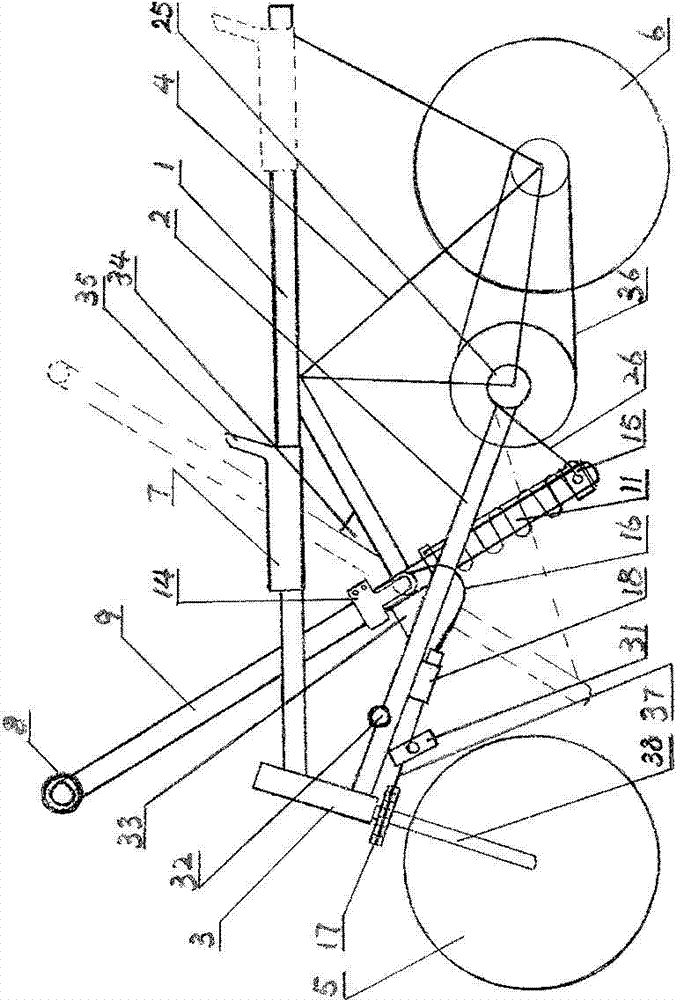
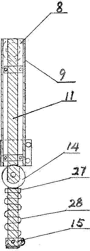
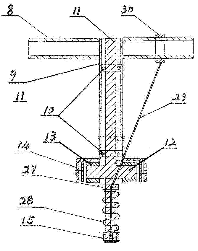
[0032] Such as figure 1 Shown, pulling of the present invention, pedal and recoil bicycle, comprise slide rail crossbeam 1, inclined beam 2, turn to concurrently power drive mechanism, walking transmission mechanism and steering transmission mechanism, slide rail crossbeam 1 and inclined beam 2 front ends are connected with front fork respectively The pipe 3 is connected, the front fork pipe 3 is inserted with a front fork 38, the front of the slide rail crossbeam 1 is low and the rear is high, the rear side lower part of the slide rail crossbeam 1 is connected with the rear end of the inclined beam 2 through the support frame 4, the front fork 38 and the support The lower part of the frame 4 is provided with front wheels 5 and rear wheels 6 respectively, slide rail beam 1 is provided with sliding seat 7, and the rear part of sliding seat 7 is provided with backrest 35, and the middle and lower part of the steering and power drive mechanism is rotatably connected to the incline...


PUM


Abstract

The invention discloses a dragging, pedaling and recoil force integrated bicycle. The front end of a sliding rail cross beam (1) and the front end of an inclined beam (2) are connected with a front fork tube (3) respectively; the lower part on the rear side of the sliding rail cross beam (1) is connected with the rear end of the inclined beam (2) through a supporting frame (4); a front wheel (5) and a rear wheel (6) are arranged on the lower part of a front fork (38) and the lower part of the supporting frame (4) respectively; a sliding seat (7) is arranged on the sliding rail cross beam (1) in a sliding manner; the middle lower part of a turning and power driving mechanism is connected to the inclined beam (2); the lower part of the turning and power driving mechanism is connected with the rear wheel (6) in a transmission manner through a walking transmission mechanism; and the middle upper part of the turning and power driving mechanism is connected with the front wheel (5) in a transmission manner through a turning transmission mechanism. The dragging, pedaling and recoil force integrated bicycle has a novel design and a simple structure and is easy to machine and manufacture; riding instead of walking is supplied to people and sporting equipment for whole body movement is also supplied to people, so the bicycle kills two birds with one stone; furthermore, the dragging, pedaling and recoil force integrated bicycle has extremely high practicability and high market potential and is easy to popularize and apply.

Description

technical field [0001] The invention relates to a bicycle, in particular to a bicycle with pulling, pedaling and recoil force for walking with coordination and cooperation of upper limbs and lower limbs. Background technique [0002] The bicycle of prior art is subject to the constraint and influence of technical standardization and use specialization for a long time always. The handlebar at the front upper part of the main body of the vehicle frame, the seat at the upper middle part and the parts such as two sets of cranks, pedals, sprockets, chains and flywheels at the middle and lower parts for driving the wheels forward, thus forming the bicycle of the basic characteristics of the prior art, Due to the limitation of the basic structure of the vehicle frame, the center of gravity of the position of the two arms and the buttocks of the person is relatively fixed, and the driving is carried out by the legs and feet of the person, which will inevitably form the following def...

Claims


Application Information

Patent Timeline
Patent Type & Authority Patents(China)
IPC IPC(8): B62M1/12
Inventor 耿康力耿昭
Owner 耿康力
Learn More