
Flow control structure of nitrogen-oxygen separation device

A flow control and nitrogen-oxygen separation technology, applied in the field of oxygen generators, can solve the problems of large gas fluctuation, automatic and precise control of nitrogen-oxygen mixed gas, and inability to output flow gas, so as to avoid being too sensitive and easy to monitor and control. Effect

Pending Publication Date: 2022-04-08
HEFEI KANGJUREN INTELLIGENT TECH
View PDF0 Cites 0 Cited by
  • Summary
  • Abstract
  • Description
  • Claims
  • Application Information

AI Technical Summary

Problems solved by technology

Since the adsorbent has the characteristic that its adsorption capacity changes with the pressure, changing its pressure can make the adsorption and desorption operation alternately, the traditional flow control structure for nitrogen and oxygen separation cannot automatically and accurately control the separation of nitrogen and oxygen mixed gas, resulting in output The gas fluctuates greatly and cannot output a stable flow of gas, so it continues to change

Method used


Image

  • Flow control structure of nitrogen-oxygen separation device
  • Flow control structure of nitrogen-oxygen separation device
  • Flow control structure of nitrogen-oxygen separation device

Examples


Embodiment Construction

[0029] The following will clearly and completely describe the technical solutions in the embodiments of the present invention with reference to the accompanying drawings in the embodiments of the present invention. Obviously, the described embodiments are only some, not all, embodiments of the present invention.

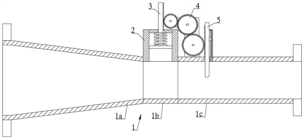
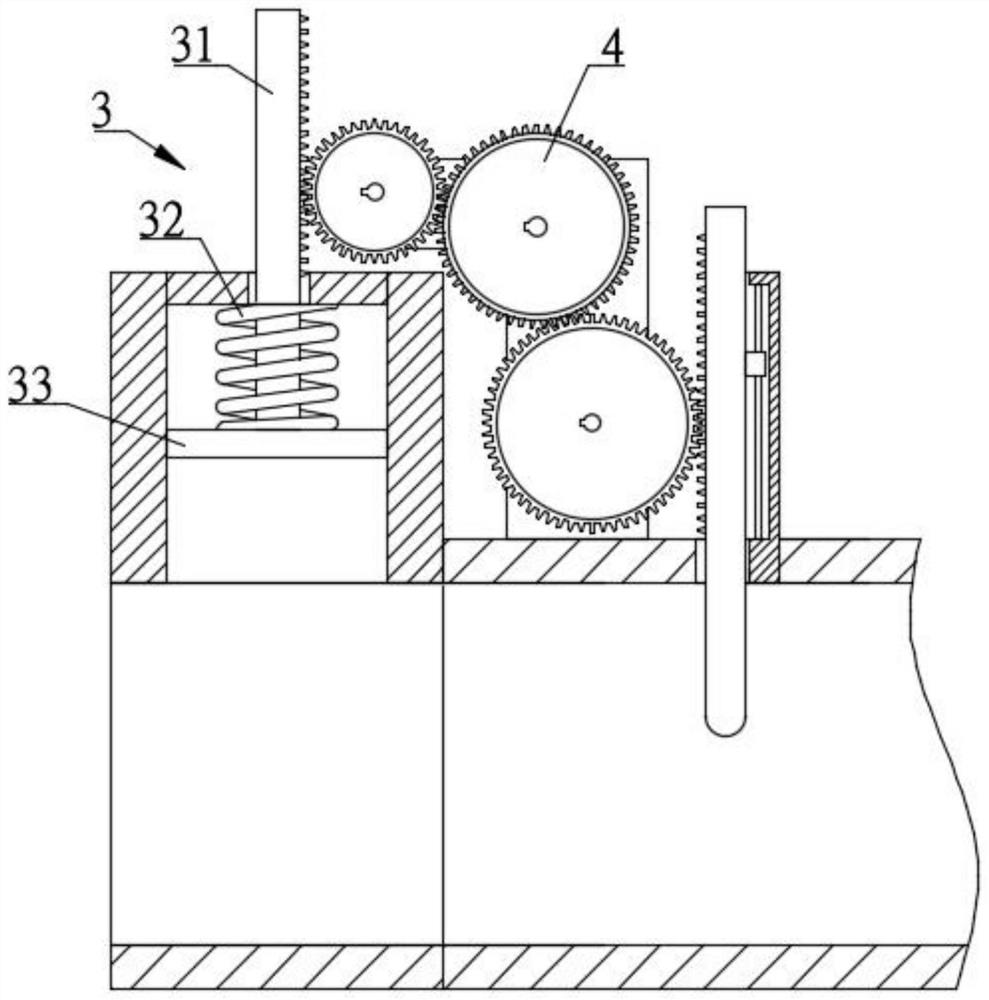
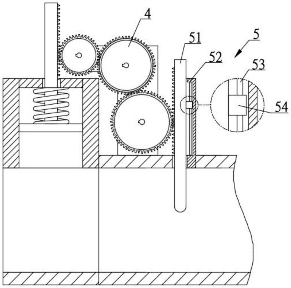
[0030] refer to Figure 1-4 , a flow control structure of a nitrogen-oxygen separation device, including a pipeline 1, a casing 2, a flow monitoring component 3, a transmission component 4 and a flow control component 5.

[0031] refer to figure 1 , the pipeline 1 is composed of three parts: the conical section 1a, the monitoring section 1b and the control section 1c, and the three parts of the conical section 1a, the monitoring section 1b and the control section 1c are integrally formed, and the setting of the conical section 1a plays a role The effect of reducing the diameter of the pipe reduces the diameter of the pipes at the monitoring section 1b and the contro...


PUM


Abstract

The invention discloses a flow control structure of a nitrogen-oxygen separation device, and relates to the technical field of oxygen generators, the flow control structure comprises a pipeline, the pipeline is composed of a conical section, a monitoring section and a control section, and the conical section, the monitoring section and the control section are integrally formed; the flow monitoring assembly is arranged on the monitoring section and is used for monitoring the gas flow in the monitoring section; the flow control assembly is arranged on the control section and used for controlling the gas flow in the control section. The transmission assembly is connected with the flow monitoring assembly and the flow control assembly and used for converting flow changes monitored by the flow monitoring assembly into flow control of the flow control assembly. The conical section, the monitoring section and the control section are arranged on the pipeline, and the conical section plays a role in reducing the pipe diameter, so that the pipe diameters at the monitoring section and the control section are reduced, and the flow is conveniently monitored and controlled.

Description

technical field [0001] The invention relates to the technical field of oxygen generators, in particular to a flow control structure of a nitrogen and oxygen separation device. Background technique [0002] Oxygen concentrator is a kind of machine for producing oxygen. Its principle is to use air separation technology. Using the adsorption properties of molecular sieves, through physical principles, a large-displacement oil-free compressor is used as the power to separate nitrogen and oxygen in the air, and finally obtain high-concentration oxygen. This type of oxygen generator produces oxygen quickly and has a high oxygen concentration, and is suitable for oxygen therapy and oxygen health care for various groups of people. Since the adsorbent has the characteristic that its adsorption capacity changes with the pressure, changing its pressure can make the adsorption and desorption operation alternately, the traditional flow control structure for nitrogen and oxygen separatio...

Claims


Application Information

Patent Timeline
Patent Type & Authority Applications(China)
IPC IPC(8): B01D53/02C01B13/02
Inventor 梁锐李昌才丁松林冷宇航段志伟吕涛张静
Owner HEFEI KANGJUREN INTELLIGENT TECH
Learn More