Drilling equipment with steering function

A kind of drilling equipment and functional technology, applied in the field of drilling equipment with steering function, can solve the problems of reducing the scope of application and not having steering function, and achieve good practical effect

Pending Publication Date: 2021-03-09
湖南九五精机有限责任公司
View PDF7 Cites 0 Cited by
  • Summary
  • Abstract
  • Description
  • Claims
  • Application Information

AI Technical Summary

Problems solved by technology

[0003] However, the current drilling device still has the following deficiencies in actual use. Because most of the existing drilling equipment does not have a steering function, it needs manual hand-held rotation to punch objects from multiple angles, thereby reducing the scope of application. , designing a drilling equipment with steering function has become an urgent problem to be solved at present

Method used


Image

  • Drilling equipment with steering function
  • Drilling equipment with steering function
  • Drilling equipment with steering function

Examples


Embodiment 1

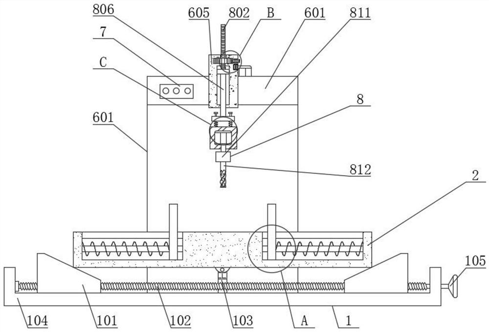
[0029] see Figure 1-7 , the present invention provides a technical solution:

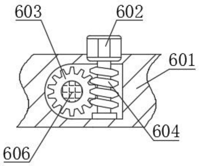
[0030] A drilling device with a steering function, comprising a support base 2, a splint 3 slidingly connected to the inside of the support base 2, a second limit rod 4 fixedly connected to the inside of the support base 2, and a first spring provided outside the second limit rod 4 5. The controller 7 and the drill-pipe steering mechanism 6, the drill-pipe steering mechanism 6 includes a side plate 601, the top inside of the side plate 601 is fixedly connected with a first motor 602, the end of the main shaft of the first motor 602 is fixedly connected with a worm 604, the worm The bottom of 604 is rotationally connected with the inner side of the bottom of side plate 601, and the inner side of the top of side plate 601 is rotationally connected with rotating shaft 606, and the outer side of rotating shaft 606 is fixedly connected with worm wheel 603, and the outer side of worm wheel 603 meshes wit...

Embodiment 2

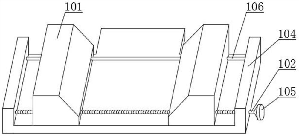
[0034] Embodiment 2: In this embodiment, the same places as in Embodiment 1 will not be repeated. The difference is that the present invention can also realize the steering of the drilling direction through the support steering mechanism 1, thereby being applicable to different drilling requirements. When working, the staff can first place the drilling object in the middle of the splint 3 on both sides of the support base 2, and the splint 3 will fix the drilling object under the action of the first spring 5. When turning, the staff turns the runner 105 , the runner 105 drives the first screw 102 to rotate, and during the rotation of the first screw 102, the first screw 102 will drive the wedge block 101 to move leftward or rightward, and the first stop rod 106 provided acts as a countermeasure against The movement direction of the wedge block 101 acts as a limiter. When the wedge blocks on both sides move to the left or right, the support seat 2 will be forced to tilt to the l...


PUM


Abstract

The invention relates to the technical field of drilling, in particular to drilling equipment with a steering function. The drilling equipment comprises a supporting base, clamping plates, second limiting rods, first springs, a controller and a drilling rod steering mechanism, wherein the clamping plates are slidably connected to the inner side of the supporting base; the second limiting rods arefixedly connected to the inner side of the supporting base; the first springs are arranged on the outer sides of the second limiting rods; the drilling rod steering mechanism comprises a side plate; afirst motor is fixedly connected to the inner side of the top end of the side plate; and a worm is fixedly connected to the tail end of a main shaft of the first motor. According to the drilling equipment, steering of the drilling rod direction can be achieved through the drilling rod steering mechanism, so that drilling in different directions is achieved; and during steering, the controller controls the first motor to rotate, the first motor drives the worm to rotate, the worm can drive a worm gear to rotate in the rotating process, the worm gear can drive a rotating shaft to rotate, the rotating shaft rotates to drive a connecting box to rotate, and the connecting box rotates to drive a drilling rod to change the direction through a connecting rod, so that the drilling rod steering method is simple and rapid.

Description

technical field [0001] The invention relates to the technical field of drilling, in particular to a drilling device with steering function. Background technique [0002] Drilling generally refers to the operation of machining a hole in a solid material with a drill bit. Common drilling equipment includes electric drills, drilling machines, etc. With the further development of processing technology, the efficiency of drilling equipment has also been greatly improved, and it has also been widely used in mechanical processing. [0003] However, the current drilling device still has the following deficiencies in actual use. Because most of the existing drilling equipment does not have a steering function, it needs manual hand-held rotation to punch objects from multiple angles, thereby reducing the scope of application. Therefore, designing a drilling device with a steering function has become an urgent problem to be solved at present. Contents of the invention [0004] The ...

Claims


Application Information

Patent Timeline
Patent Type & Authority Applications(China)
IPC IPC(8): B23Q1/44B23Q5/22B23Q5/28
CPCB23Q5/22B23Q1/44B23Q5/28
Inventor 吴向忠高明铭冉晓茹李军舰朱坤彭晓云谭幸运朱宏杰
Owner 湖南九五精机有限责任公司
Why Eureka
Try Eureka