A New Diesel Engine Valve Behavior and Cam Stress Measuring Device

A stress measurement, diesel engine technology, applied in the direction of measuring devices, internal combustion engine testing, engine testing, etc., can solve problems such as greater than the equivalent cam lift, parts processing errors, valve crushing, etc., to achieve wide application range and simple structure Effect

Active Publication Date: 2019-05-14
CHINA NORTH ENGINE INST TIANJIN
View PDF4 Cites 0 Cited by
  • Summary
  • Abstract
  • Description
  • Claims
  • Application Information

AI Technical Summary

Problems solved by technology

[0003] However, during the actual operation of the engine, the valve does not move according to the law stipulated by the cam profile, and the opening time of the valve is delayed. Again, the actual valve lift is greater than the equivalent cam lift. This phenomenon will produce a series of consequences: repeated impacts between the valve and the valve seat will aggravate the wear and tear, and even break the valve or cause it to be stretched and deformed; There will also be impacts between the various parts of the mechanism, resulting in severe wear and noise; on an internal combustion engine with a large compression ratio, the valve rebound may cause the valve to collide with the piston; in severe cases, it will affect the time-section of the valve and the machine. Performance
[0004] The cam surface and the bottom surface of the tappet are a pair of friction pairs. Due to the machining error of the parts and the bending deformation of the camshaft, it is often impossible to ensure that the cam surface is in full width contact with the tappet surface during work, resulting in abnormal wear

Method used


Image

  • A New Diesel Engine Valve Behavior and Cam Stress Measuring Device
  • A New Diesel Engine Valve Behavior and Cam Stress Measuring Device

Examples


Embodiment Construction

[0020] It should be noted that, in the case of no conflict, the embodiments of the present invention and the features in the embodiments can be combined with each other.

[0021] The present invention will be described in detail below with reference to the accompanying drawings and examples.

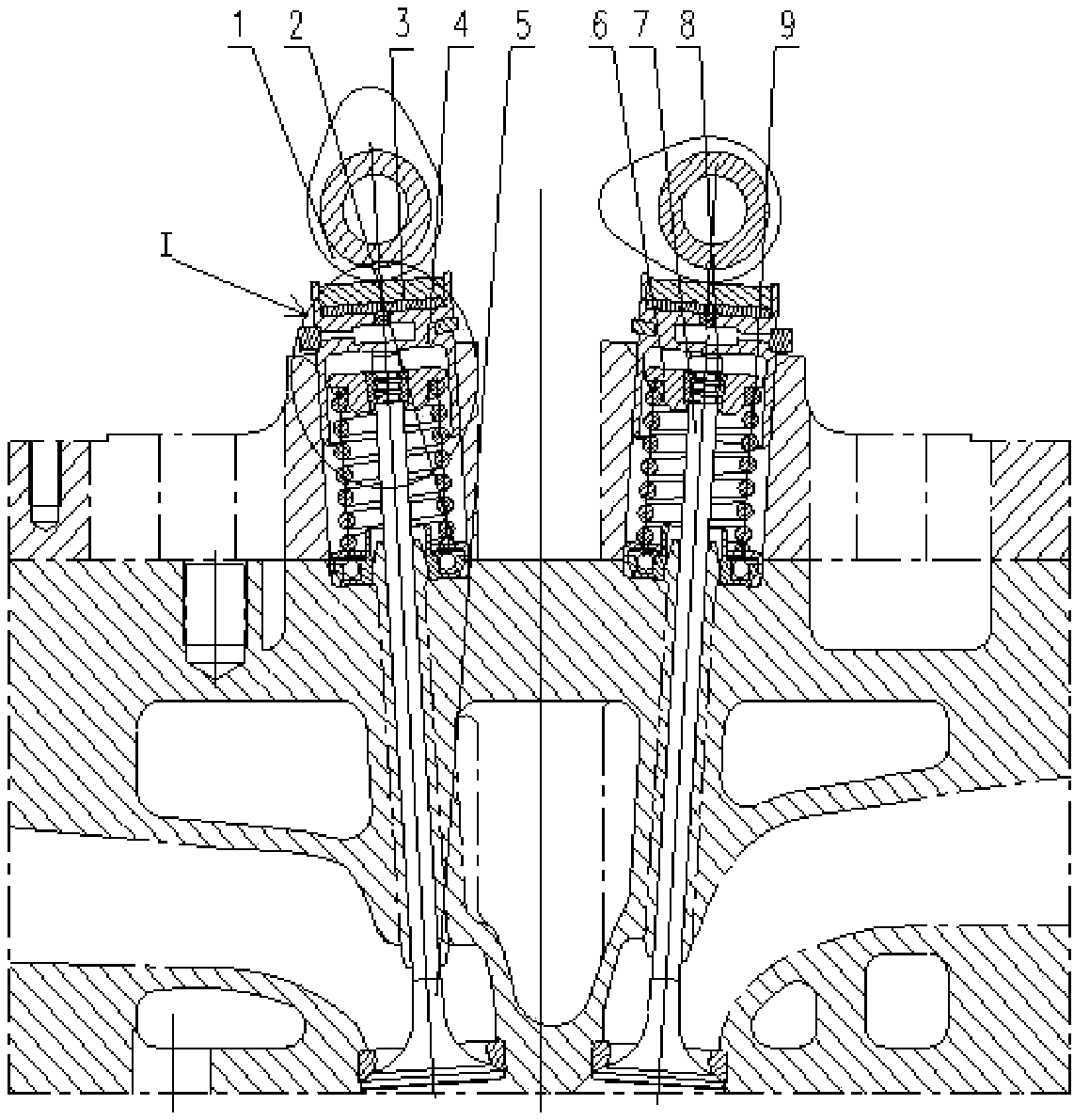
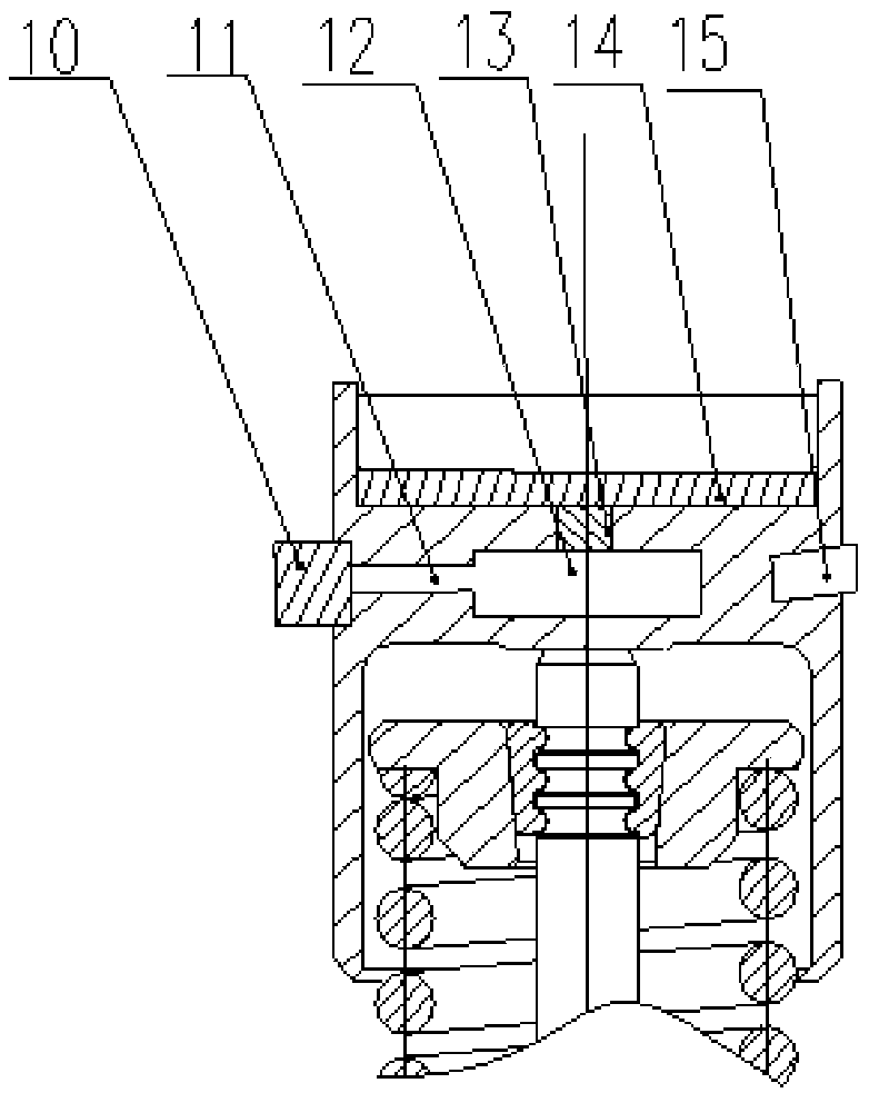
[0022] Such as figure 1 and figure 2 As shown, a novel diesel engine valve behavior and cam stress measuring device includes a camshaft 1 and a guide sleeve 4, the camshaft 1 is located above the guide sleeve 4, and a gap adjustment piece 3 is installed between the guide sleeve 4, the The guide cylinder 4 is provided with a precision pressure sensor 10, a sealed oil passage 11, a pressure storage chamber 12, an oil pump piston 13, a support surface 14 and a wireless displacement sensor 15, and the precision pressure sensor 10 and the wireless displacement sensor 15 are respectively installed on the The upper part of the two side walls of the guide cylinder 4, the support surface 14 is...


PUM


Abstract

The invention provides a novel diesel engine valve behavior and cam stress measuring device comprising camshafts and guide cylinders. The camshafts are disposed on the upper parts of the guide cylinders, and gap adjusting sheets are disposed between the camshafts and the guide cylinders. The guide cylinders are provided with precision pressure sensors, sealed oil ducts, pressure accumulation cavities, oil pumping pistons, supporting surfaces, and wireless displacement sensors. The precision pressure sensors and the wireless displacement sensors are disposed on the upper parts of the two side walls of the guide cylinders. The supporting surfaces are disposed in the guide cylinders on the lower parts of the gap adjusting sheets. The oil pumping pistons are disposed under the supporting surfaces, and are connected with the pressure accumulation cavities, and the precision pressure sensors are connected with the pressure accumulation cavities by the sealed oil ducts. The novel diesel engine valve behavior and cam stress measuring device is advantageous in that the precision pressure sensors are used to measure the action forces of the cams and the guide cylinders under an actual operation working condition of an engine, and the wireless displacement sensors are used to measure and calculate valve displacement, speed, acceleration, and saltus after installation, and then a valve motion rule under an actual condition is acquired; the structure of the device is simple, and the expansion application range of the device is wide.

Description

technical field [0001] The invention belongs to the technical field of valve measurement, in particular to a novel diesel engine valve behavior and cam stress measurement device. Background technique [0002] The task of the valve mechanism is to ensure that the valve is opened and closed at the specified time. The air flow should be smooth when it is opened, and the high-pressure gas in the cylinder should be sealed when it is closed. When the engine is running at high speed, the above actions are repeated at a high frequency. In this case, it is required that the valve train should be able to work reliably for a long time. [0003] However, during the actual operation of the engine, the valve does not move according to the law stipulated by the cam profile, and the opening time of the valve is delayed. Again, the actual valve lift is greater than the equivalent cam lift. This phenomenon will produce a series of consequences: repeated impacts between the valve and the valv...

Claims


Application Information

Patent Timeline
Patent Type & Authority Patents(China)
IPC IPC(8): G01M15/04
CPCG01M15/042
Inventor 程秀围王子玉王国莹许文燕王红丽任庆霜赵斌
Owner CHINA NORTH ENGINE INST TIANJIN
Why Eureka
Try Eureka