Tensile fatigue test machine

A fatigue testing machine, clamping head technology, applied in the direction of testing material strength by applying repetitive force/pulsation force, testing material strength by applying stable tension/compression, measuring devices, etc.

Active Publication Date: 2017-06-09
HARBIN INST OF TECH
View PDF8 Cites 11 Cited by
  • Summary
  • Abstract
  • Description
  • Claims
  • Application Information

AI Technical Summary

Problems solved by technology

[0006] The technical problem to be solved by the present invention is to solve the problem that t...

Method used


Image

  • Tensile fatigue test machine
  • Tensile fatigue test machine
  • Tensile fatigue test machine

Examples


Embodiment 1

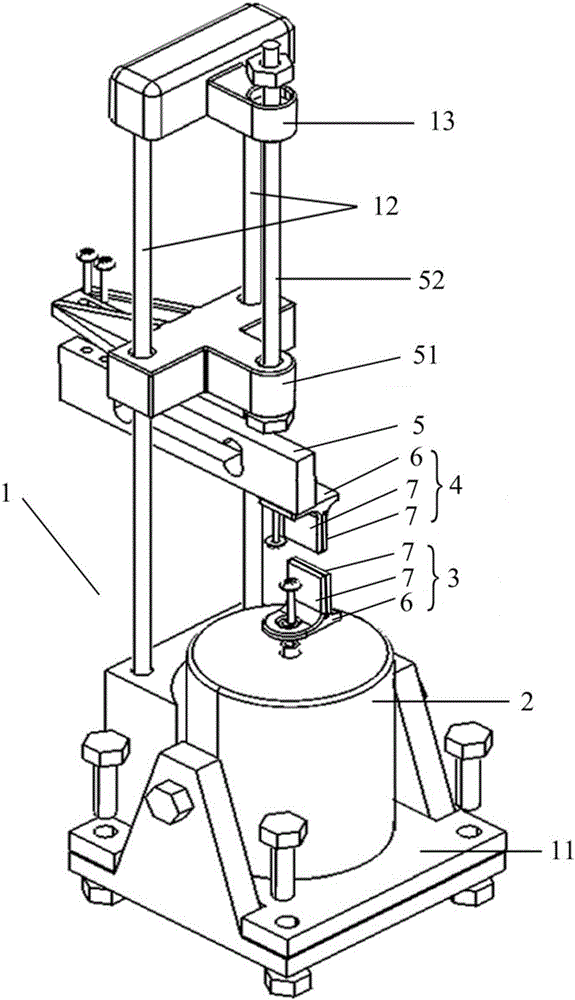
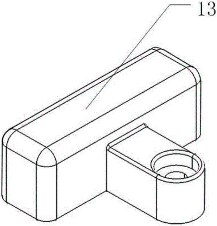
[0034] The tensile fatigue testing machine provided by the embodiment of the present invention includes a support 1 , an exciter 2 , a lower clamping head 3 , an upper clamping head 4 and a force sensor 5 . Such as figure 1 As shown, the support 1 includes a base 11 and a support column 12, the support column 12 is installed on the base 11, and a support beam 13 is provided at the top. Both the exciter 2 and the force sensor 5 are arranged on the support 1 , the exciter 2 is fixed on the base 11 , and the force sensor 5 is arranged on the column 12 of the support. The lower clamping head 3 is connected with the ejector rod of the vibrator 2 and can move synchronously with the ejector rod; the upper clamping head 4 is connected with the force sensor 5 and is fixed below the force sensor 5 for transmitting the force to the The force sensor 5 ; the lower clamping head 3 and the upper clamping head 4 are arranged at intervals along the axial direction of the ejector rod.

[0035...

Embodiment 2

[0049] The second example is basically the same as the first example, and the similarities will not be repeated. The difference lies in:

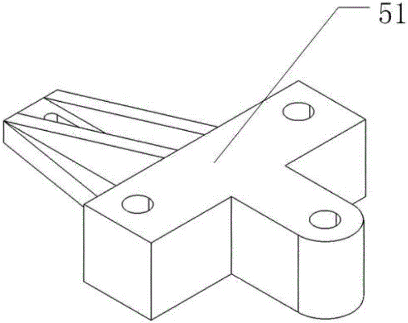
[0050] In the present embodiment, the inner wall of the through hole of the adjusting part of the sensor frame 51 is provided with threads. The parts are threaded through holes, the head of the bolt is stuck on the upper part of the bracket beam 13, and the lower end is threaded with the sensor frame 51, and the sensor frame 51 is suspended below the bracket beam 13. When adjusting, turn the second adjustment bolt to change the position of the sensor frame 51 on the bolt. The upper position can change the sensor frame 51 suspension height.

[0051] Such as Figure 4 As shown, the clamping portion of the lower clamping head 3 includes two clips 7 that can move relative to the fixed portion 6, and the two clips 7 can be disassembled, wherein one clip 7 is provided with a lateral protrusion for anti-slip And anti-skid groove, another clip 7 ...


PUM


Abstract

The invention relates to the technical field of a fatigue test device, in particular to a tensile fatigue test machine. The tensile fatigue test machine comprises a bracket, a vibration exciter, a lower clamping head, an upper clamping head and a force sensor; the vibration exciter and the force sensor are arranged on the bracket; the lower clamping head is connected with a top rod of the vibration exciter and can synchronous move along with the top; the upper clamping head is connected with the force sensor and used for conducting the stress condition to the force sensor; the lower clamping head and the upper clamping head are arranged at intervals in the axial direction of the top rod. The tensile fatigue test machine solves the problem that the tensile fatigue test device for monofilaments does not exist in the prior art; the test machine is small in volume and high in flexibility; each accessory can be replaced according to the requirement, is high in matching property and wide in application range, and has high stability and reusability.

Description

technical field [0001] The invention relates to the technical field of fatigue testing devices, in particular to a tensile fatigue testing machine. Background technique [0002] Under the action of external alternating stress, the parts will be damaged by fatigue after a period of time. Therefore, it is of great significance to study material fatigue and carry out fatigue tests. The data of the fatigue test results can be analyzed by conducting multiple tests on parts or materials, and then obtain the fatigue life value closest to the real one. At present, there are many kinds of fatigue testing machines for detecting the fatigue life of parts at home and abroad. The fatigue testing machine has become an important tool for research institutes and scholars to study and test the fatigue performance of materials. [0003] Fiber composite material is a kind of material with good performance. Under the fatigue load of its structure, the initial damage generated inside will gra...

Claims


Application Information

Patent Timeline
IPC IPC(8): G01N3/08G01N3/32
CPCG01N3/08G01N3/32G01N2203/0017G01N2203/0073
Inventor 孙新杨果立成张翊东张川张莉孙锐坚
Owner HARBIN INST OF TECH
Why Eureka
Try Eureka