
Zooming imaging device

An imaging device and focusing technology, which is applied in the field of zoom imaging, can solve the problems of inconvenient miniaturization of three-dimensional imaging devices, low consistency of driving circuits, and large power consumption, etc., and achieve the advantages of facilitating processing, reducing weight, and saving space Effect

Inactive Publication Date: 2017-06-09
珠海康弘健康投资管理有限公司
View PDF4 Cites 0 Cited by
  • Summary
  • Abstract
  • Description
  • Claims
  • Application Information

AI Technical Summary

Problems solved by technology

Combining the current 3D imaging technology with the optical zoom device requires 2 image sensor chips, the drive circuit is not consistent, the power consumption is large, and the overall volume of the device is larger, which is very inconvenient for the miniaturization of the 3D imaging device

Method used


Image

  • Zooming imaging device
  • Zooming imaging device
  • Zooming imaging device

Examples


Embodiment Construction

[0044] First embodiment of zoom imaging device:

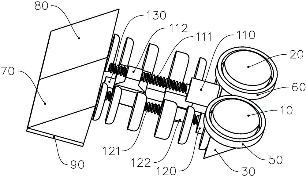
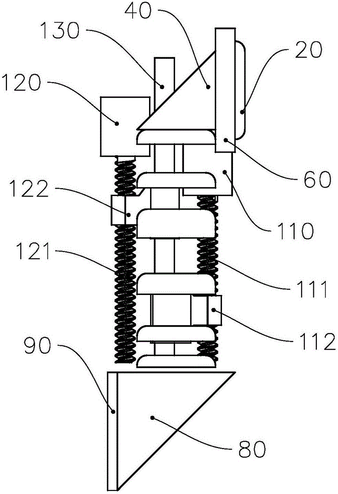
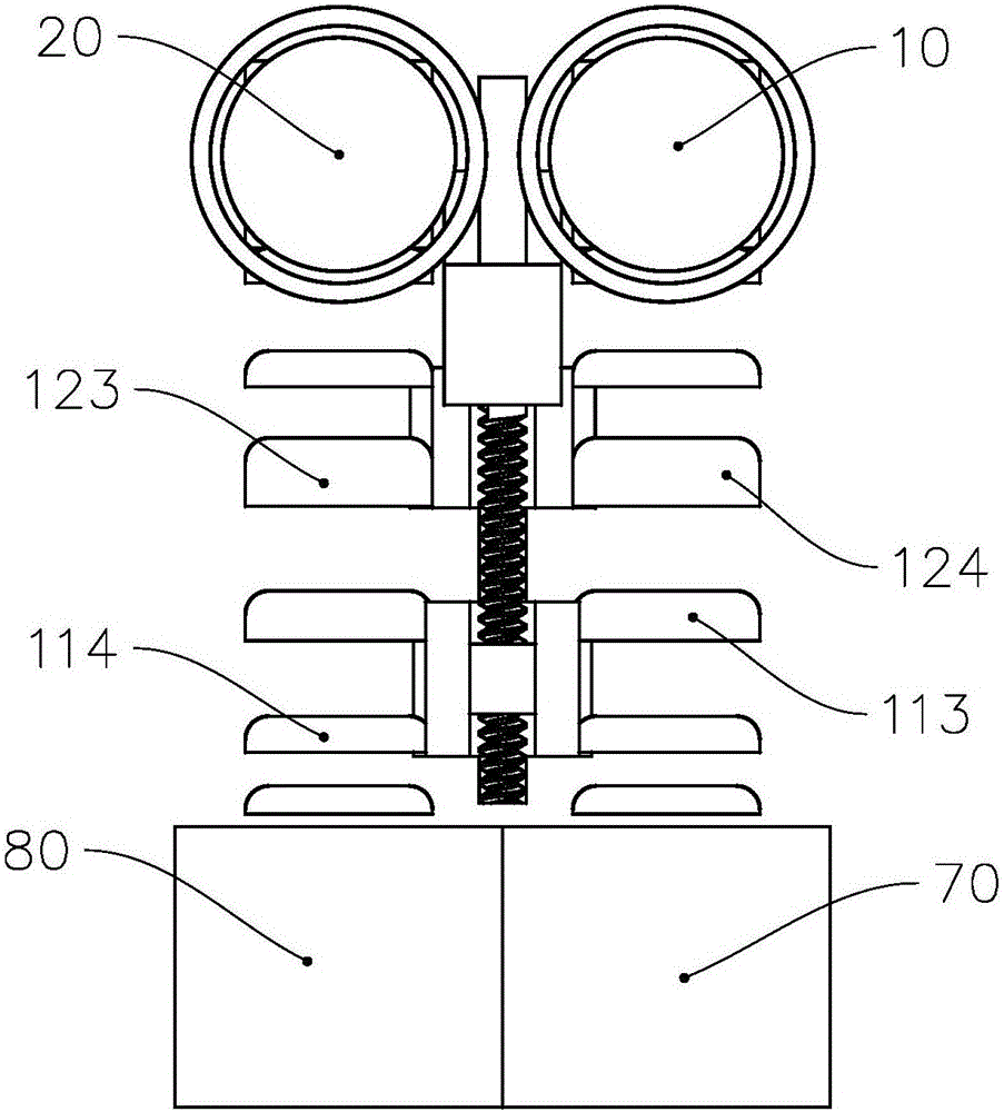
[0045] see figure 1 , figure 1 It is a structural diagram of the first embodiment of the zoom imaging device. The zoom imaging device of this embodiment includes an image sensor 90 , a first objective lens 10 , a second objective lens 20 and a zoom device 100 . The first objective lens 10 and the second objective lens 20 are arranged on both sides of the image sensor 90, and the optical axes of the first objective lens 10 and the second objective lens 20 are all perpendicular to the target surface of the image sensor 90, between the first objective lens 10 and the image sensor 90 A first deflection prism 30 and a third deflection prism 70 are arranged between them, and a zoom device 100 is also arranged between the first deflection prism 30 and the third deflection prism 70. The light beam emitted by the first objective lens 10 passes through the first deflection prism 30 It enters the zoom device 100 , passes through the zoo...


PUM


Abstract

The invention provides a zooming imaging device with a small size and capable of adjusting the focal length; the zooming imaging device comprises an image sensor, a first object lens, a second object lens and a zooming unit; the first and second object lenses are arranged on two sides of the image sensor; a first deflect prism and a third deflect prism are arranged between the first object lens and the image sensor; the zooming unit is arranged between the first and third deflect prisms; a second deflect prism and a fourth deflect prism are arranged between the second object lens and the image sensor. The zooming imaging device can adjust the focal length of three dimensional imaging equipment, is simplified in structure, lowered in cost, and can increase the endurance ability.

Description

technical field [0001] The invention relates to the field of zoom imaging, in particular to a zoom imaging device. Background technique [0002] With the development of multimedia technology, people begin to study video technologies with three-dimensional images, so that the captured videos have three-dimensional images, and these videos are usually called 3D videos. At present, the 3D imaging technology adopted by most of the 3D imaging devices on the market is to use the objective lens for the left eye and the objective lens for the right eye with parallax to collect images. imaging to achieve 3D imaging. However, such an imaging device is provided with two image sensors, and its driving circuit is not consistent, and because the 3D imaging device is bulky, it is inconvenient to carry, and the price of the 3D imaging device is high, and its market penetration is not high. [0003] Another current 3D imaging device uses a parallax objective lens for the left eye and an ob...

Claims


Application Information

Patent Timeline
IPC IPC(8): H04N13/02G02B7/04G03B13/34G03B17/12G03B35/08
CPCH04N13/20H04N13/296G02B7/04G03B13/34G03B17/12G03B35/08
Inventor 胡善云刘鹏
Owner 珠海康弘健康投资管理有限公司
Learn More