Mixed-dentition maxillary occlusal pad molar distal jet

A technology of occlusal pad and replacement dentition, which is applied in the fields of dentistry, orthodontics, orthodontics, etc. It can solve problems such as insufficient retention and anchorage, limited treatment effect, and delayed treatment timing to achieve high anchorage. , reduce movement, and expand the effect of dental arch width

Active Publication Date: 2017-06-13
AFFILIATED STOMATOLOGICAL HOSPITAL OF NANJING MEDICAL UNIV
View PDF7 Cites 9 Cited by
  • Summary
  • Abstract
  • Description
  • Claims
  • Application Information

AI Technical Summary

Problems solved by technology

[0006] The purpose of the present invention is to provide a maxillary occlusal pad type molar remoter for the dentition period, which is suitable for the dentition period, high-efficiency and distal overall movement of the maxillary first molars, and solves the problem of movable appliances existing in the prior art due to retention. and insufficient anchorage are not suitable for the replacement dentition stage with fewer teeth, delaying the timing of treatment, and limiting the treatment effect, etc.

Method used


Image

  • Mixed-dentition maxillary occlusal pad molar distal jet
  • Mixed-dentition maxillary occlusal pad molar distal jet
  • Mixed-dentition maxillary occlusal pad molar distal jet

Examples


Embodiment 1

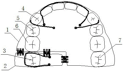
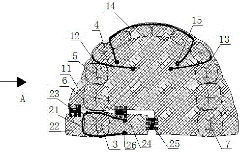
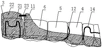
[0029] A kind of maxillary occlusal pad type molar remote mover in the replacement dentition period, such as figure 1 , including a fixed fulcrum assembly 1 and a distal displacement assembly 2 for moving the first molar 3 to be displaced, such as figure 2 and image 3 , the fixed fulcrum assembly 1 includes the base 11 for the fulcrum, the interproximal hook one 12 for the fulcrum, the interproximal hook two 13 for the fulcrum and the hyperbolic labial bow 14 for the fulcrum, as Figure 4 One side of the hyperbolic labial arch 14 for the fulcrum is embedded in the base 11 for the fulcrum, and the other side of the hyperbolic labial arch 14 for the fulcrum is set on the labial side of the dentition, and the fulcrum is embedded in the base 11 to be removed. For all the dentition except the first molar 3, interproximal hook 12 for fulcrum and interproximal hook 2 13 for fulcrum are respectively set on both sides of base 11 for fulcrum, and interproximal hook 12 for fulcrum, in...

Embodiment 2

[0043] The structure of embodiment two is basically the same as that of embodiment one, and the difference between embodiment two and embodiment one is that: as Figure 5 , the distal displacement assembly 2 includes a left distal displacement assembly 2 for displacing the left first molar 3 to be displaced and a right distal displacement assembly 2 for displacing the right first molar 3 to be displaced Displacement component 2, the base 22 for displacement of the left distal displacement component 2 embeds one side of the middle auger 25 for displacement, and the other side of the middle auger 25 for displacement is embedded in the right side The base 22 for displacement of the distal displacement component 2 and the intermediate helical expander 25 for displacement are arranged at the midpalatal suture.

[0044] Unlike Embodiment 1, which is applicable to the distal displacement of the first molar 3 to be displaced on one side, in Embodiment 2, through the left distal displa...


PUM


Abstract

The invention provides a mixed-dentition maxillary occlusal pad molar distal jet. The mixed-dentition maxillary occlusal pad molar distal jet comprises a fixed support component and a distoplacement component used for moving a first molar tooth to be displaced, wherein the fixed support component comprises a support base plate, a support adjacent hook I, a support adjacent hook II and a support hyperbolic lip bow; the distoplacement component comprises a displacement arrow clamp, a displacement base plate, a displacement buccal screw expander and a displacement palatal screw expander. The mixed-dentition maxillary occlusal pad molar distal jet can achieve the function of effective distal integral movement of the maxillary first molar tooth. The screw expanders are placed on an impedance center plane of the first molar tooth to be displaced, the force is gradually increased to finish distal movement correction of the first molar tooth to be displaced; the support base plate is stably bonded to a gum to provide the maximum anchorage force, so that unnecessary movement of other teeth is reduced.

Description

technical field [0001] The invention relates to a maxillary occlusal pad type molar remoter in the dentition period. Background technique [0002] The eruption and replacement process of teeth is promoted by many factors. During the replacement period, the caries or premature loss of the second deciduous molars often lead to the mesial movement of the first molars, resulting in the impaction of the second premolars and affecting the normal replacement of teeth. Early intervention is needed to move the mesially moved first molars far away to promote the normal eruption of permanent teeth and avoid the occurrence of complex malocclusion. In the replacement period, there are relatively few teeth that can provide anchorage, and the retention of the appliance is insufficient, and the mesially moved first molars cannot effectively move to the normal position. Therefore, it is urgent to design an orthodontic appliance that has relatively less requirements for anchorage teeth, les...

Claims


Application Information

Patent Timeline
Patent Type & Authority Applications(China)
IPC IPC(8): A61C7/00A61C7/10
CPCA61C7/00A61C7/10A61C2204/00
Inventor 陈慧霞谢慧黄优夏文倩韩晓王林李媛秦燕军顾洛章非敏张正东
Owner AFFILIATED STOMATOLOGICAL HOSPITAL OF NANJING MEDICAL UNIV
Why Eureka
Try Eureka