Cutting fixture and using method thereof

A tooling and cutting technology, applied in shearing devices, manufacturing tools, metal processing equipment, etc., can solve the problems of tool wear, waste of resources, small blades, etc., to ensure cutting quality, ensure cutting accuracy, and avoid waste of resources. Effect

Inactive Publication Date: 2017-06-13
TAICANG HAIJIA VEHICLE FITTINGS
View PDF10 Cites 1 Cited by
  • Summary
  • Abstract
  • Description
  • Claims
  • Application Information

AI Technical Summary

Problems solved by technology

Existing cutting tools mostly adopt the form of a switch knife. On the one hand, the blade of the switch knife is relatively large, but the actual blade part is small. Once a part is damaged, the entire blade needs to be replaced, which is easy to cause waste of resources; on the other hand, the switch knife One operation can only achieve one cut, and the cutting precision is not easy to control, resulting in unsatisfactory work efficiency and precision
Especially when cutting metals with high viscosity such as aluminum alloy, it is more likely to cause tool wear and affect dimensional accuracy

Method used


Image

  • Cutting fixture and using method thereof
  • Cutting fixture and using method thereof
  • Cutting fixture and using method thereof

Examples


Embodiment Construction

[0037] In order to make the object, technical solution and advantages of the present invention clearer, the present invention will be further described in detail below in conjunction with specific embodiments. It should be understood that the specific embodiments described here are only used to explain the present invention, not to limit the present invention.

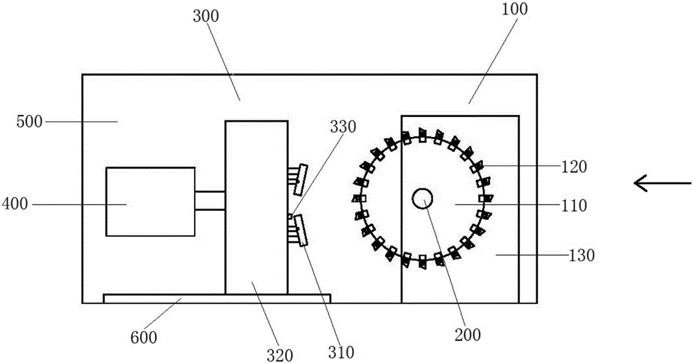
[0038] Such as figure 1 As shown, the cutting tool generally includes a cutting part 100 , a first driving device 200 , a workpiece fixing part 300 and a second driving device 400 . Wherein, the cutting part 100 comprises a disc-shaped knife rest 110 and a plurality of blades 120 detachably mounted on the outer circumference of the disc-shaped knife rest 110, and the edge of each blade 120 is along the direction away from the disc-shaped knife rest 110. The direction of the center of the circle extends radially. exist figure 1 In the illustrated embodiment, a total of 24 blades 120 are mounted on the outer circumfer...


PUM

PropertyMeasurementUnit
thicknessaaaaaaaaaa

Abstract

The invention discloses a cutting fixture. The cutting fixture comprises a cutting part, a first driving device, a workpiece fixing part and a second driving device. The cutting part comprises a disk-shaped knife rest and multiple blades installed on the outer circumference of the disk-shaped knife rest. The cutting edge of each blade is radially extended along the direction deviated from the circle center of the disk-shaped knife rest. The first driving device is connected with the circle center of the disk-shaped knife rest so as to drive the disk-shaped knife rest to be rotated by using the circle center as the axis. The workpiece fixing part comprises a clamp for fixing the workpiece. The to-be-cut face of the workpiece and the blades are positioned on the same plane. The second driving device is connected with the workpiece fixing part so as to push the workpiece fixing part to be close to or away from the cutting part. The cutting fixture is capable of effectively saving the cutting cost, and guaranteeing the cutting precision and the whole cutting quality. The invention further discloses a using method for the cutting fixture.

Description

technical field [0001] The invention relates to the field of mechanical processing, in particular to a cutting tool and a using method thereof. Background technique [0002] Cutting tooling is one of the commonly used tools in the field of machining. Existing cutting tools mostly adopt the form of a switch knife. On the one hand, the blade of the switch knife is relatively large, but the actual blade part is small. Once a part is damaged, the entire blade needs to be replaced, which is easy to cause waste of resources; on the other hand, the switch knife One operation can only achieve one cut, and the cutting precision is not easy to control, resulting in unsatisfactory work efficiency and precision. Especially when cutting metals with high viscosity such as aluminum alloy, it is more likely to cause tool wear and affect dimensional accuracy. [0003] Therefore, there is an urgent need to develop an economical and easy-to-use cutting tool. Contents of the invention [0...

Claims


Application Information

Patent Timeline
Patent Type & Authority Applications(China)
IPC IPC(8): B23D31/00B23D35/00
CPCB23D31/00B23D35/002
Inventor 陈振延
Owner TAICANG HAIJIA VEHICLE FITTINGS
Why Eureka
Try Eureka