Application method for clamping device of electric cabinet

A technology of clamping device and electrical cabinet, which is applied in positioning device, clamping, supporting and other directions, can solve the problems of high cost of clamping device, easy vibration or sliding, deviation of drilling direction, etc., and achieves convenient operation and application. Wide range, stable drilling effect

Inactive Publication Date: 2017-06-13
CHENGDU ZHENZHONG ELECTRIC
View PDF6 Cites 8 Cited by
  • Summary
  • Abstract
  • Description
  • Claims
  • Application Information

AI Technical Summary

Problems solved by technology

[0003] The technical problem to be solved by the present invention is that vibration or sliding is likely to occur during the drilling process of the electrical cabinet, and it is easy to cause the drilling direction to deviate, and the cost of designing different clamping devices for electrical cabinets of different sizes is too high. The purpose is to Provide the use method of the clamping device suitable for electrical cabinets to solve the above problems

Method used


Image

  • Application method for clamping device of electric cabinet
  • Application method for clamping device of electric cabinet

Examples


Embodiment 1

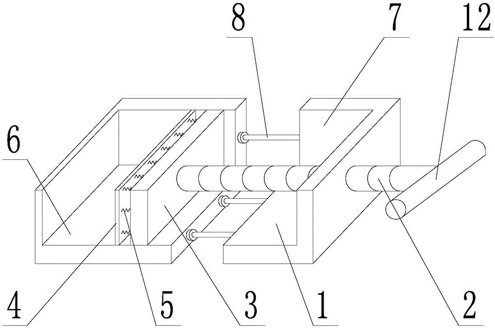
[0025] Such as Figure 1 ~ Figure 2 As shown, the method of using the clamping device suitable for electrical cabinets includes the following steps:

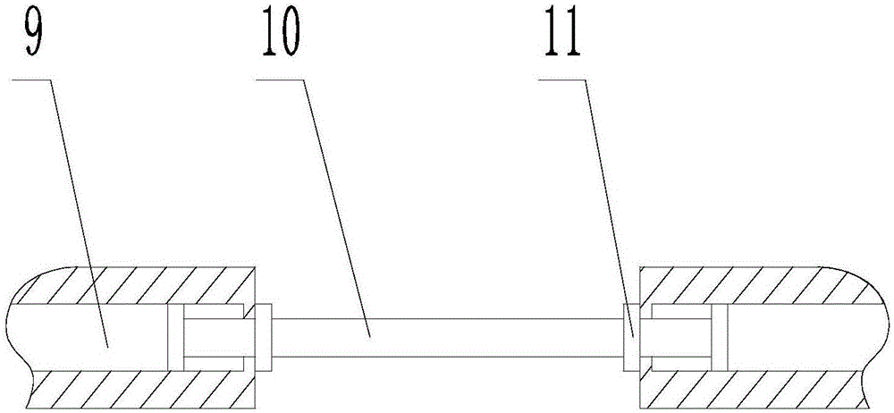
[0026] S1: Place the base 1 on the workbench or the ground, a screw 2 is provided through one side of the base 1, and a threaded hole matching the thread of the screw 2 is provided on the base 1, and the base 1 includes a bottom plate 6 and a side plate 7. Both the base plate 6 and the side plate 7 are provided with a telescopic mechanism 8. The telescopic mechanism 8 includes a guide groove 9 and a telescopic rod 10. The telescopic rod 10 is located in the guide groove 9, and the telescopic rod 10 can move along the guide groove 9. The telescopic rod 10 10. The size of both ends is larger than the opening size of the guide groove 9. Pull the telescopic rod out of the guide groove to increase the size of the base, which is suitable for larger electrical cabinets; push the telescopic rod into the guide groove to reduce the size o...

Embodiment 2

[0034] The difference between this embodiment and Embodiment 1 is that the end of the screw rod 2 outside the base 1 is provided with a driving device (not shown in the figure), and the driving device controls the rotation direction and speed of the screw rod, so that the pressing plate 3 and damping plate 4 advance or retreat along the screw rod.


PUM


Abstract

The invention discloses an application method for a clamping device of an electric cabinet. The steps of the application method comprises S1, placing a base on the work table or floor and arranging a screw rod running through one side of the base; S2, arranging a pressing plate at the end of the screw rod in the base, when rotating the screw rod, driving the pressing plate to move along the axis of the screw rod by rotating the screw rod; S3, arranging a damping plate at the other end, away from the screw rod, of the pressing plate, and installing an elastic element between the pressing plate and the damping plate; S4, adjusting the length of a base plate of the base and a side plate, and placing the electric cabinet on the base plate of the base; S5, rotating the screw rod to make the plate fit with the electric cabinet and pressing the electric cabinet tightly for drilling a hole; S6, after drilling the hole, rotating the screw rod oppositely to make the damping plate away from the electric tightly to release the electric cabinet. The application method for clamping device of an electric cabinet has the advantages that the drilling hole is more stable, installation accuracy is improved and the operation is convenient.

Description

technical field [0001] The invention relates to a clamping device, in particular to a method for using the clamping device suitable for an electrical cabinet. Background technique [0002] Assembled structures and combined units are usually used in the production process of electrical cabinets, which have the advantages of high safety, strong reliability, reasonable layout, convenience and flexibility. After the outer frame of the electrical cabinet is assembled, in order to facilitate the heat dissipation of the components in the electrical cabinet, or to install partitions in the cabinet, it is usually necessary to drill holes in the outer frame of the assembled electrical cabinet, but during the drilling process , The electrical cabinet is easy to vibrate or slide under the force of the drill bit, causing the drilling direction to deviate, and the cost of designing different clamping devices for electrical cabinets of different sizes is too high. Contents of the inventi...

Claims


Application Information

Patent Timeline
Patent Type & Authority Applications(China)
IPC IPC(8): B23Q3/06
CPCB23Q3/062
Inventor 王刚唐良华蒋继荣张仁明
Owner CHENGDU ZHENZHONG ELECTRIC
Why Eureka
Try Eureka