Electric head die clearance adjusting device for blowing machine

An adjustment device and blow molding machine technology, applied in the field of blow molding machinery, can solve the problems of manufacturing, assembly, use, daily management and maintenance, complex structure, etc., achieve good energy saving effect, avoid time lag, and facilitate manufacturing and assembly Effect

Active Publication Date: 2017-06-13
SUZHOU TONGDA MACHINERY
View PDF15 Cites 15 Cited by
  • Summary
  • Abstract
  • Description
  • Claims
  • Application Information

AI Technical Summary

Problems solved by technology

[0007] However, by reading the full text of the above-mentioned CN101966750B, it can be seen that: due to the need to use forward and reverse drive motors (two motors), clutch reversing device, speed reducer and the transmission connection between the forward and reverse drive motors and the clutch reversing device Two synchronous belts, etc. (see paragraph 0026 of the specification of this patent), so the structure is relatively complicated, and there are corresponding troubles in manufacture, assembly, use and daily management and maintenance

Method used


Image

  • Electric head die clearance adjusting device for blowing machine
  • Electric head die clearance adjusting device for blowing machine
  • Electric head die clearance adjusting device for blowing machine

Examples


Embodiment

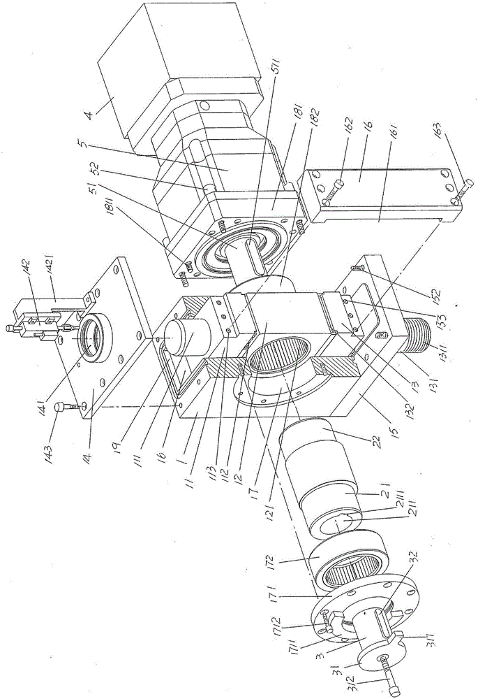
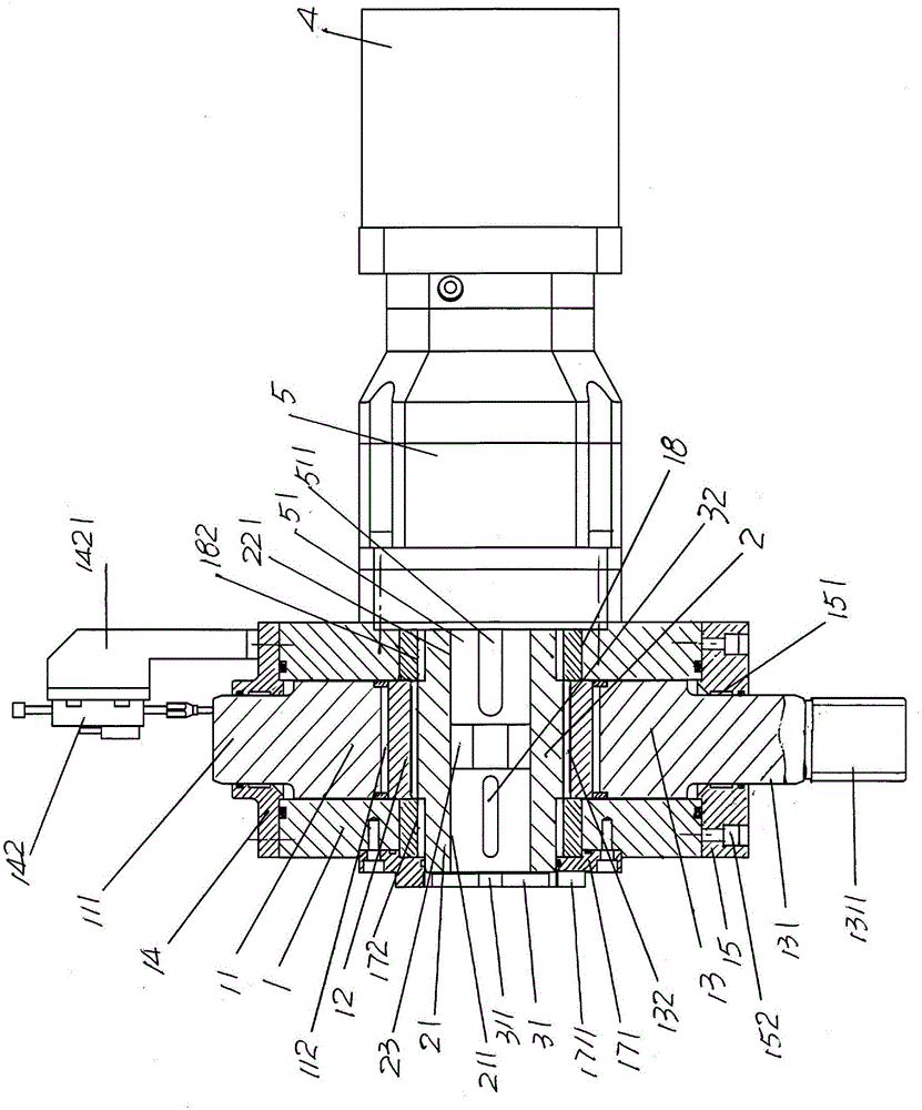
[0026] See figure 1 and figure 2, showing a box body 1, in which an upper slider 11, a cam sliding seat 12 and a slider 13 are sequentially arranged from top to bottom in the box body 1, and at the center of the upper side of the upper slider 11 There is an upper slider guide post 111 at the position, and there is a slider guide post 131 at the center of the lower side of the lower slider 13. The upper side of the cam sliding seat 12 is slidably matched with the upper slider 111, and the cam slides Seat 12 is slidably matched with lower slider 13 toward the side downwards, and an upper case cover 14 is fixed by upper case cover fixing screw 143 on the top of casing 1, and is fixed by lower case cover fixing screw 152 at the bottom of casing 1. The lower case cover 15 is respectively equipped with a slider fixing plate 16 at positions corresponding to the front side and the rear side of the cam sliding seat 12, the upper end of the slider fixing plate 16 is fixed with the upp...


PUM


Abstract

The invention discloses an electric head die clearance adjusting device for a blowing machine. The device comprises a box body, a cam and an axle cover sleeve, wherein an upper slide block, a cam sliding seat and a lower slide box are arranged in the box body, an upper box cover is arranged at the top of the box body, and a lower box cover is arranged at the bottom of the box body; slide block fixing plates are arranged at positions corresponding to the front side and rear side of the cam sliding seat; a box body left bearing chamber is formed in the left side of the box body; a left bearing cap is arranged at a position on the left side of the box body left bearing chamber; a box body right bearing chamber is formed in the right side of the box body; a right bearing cap is arranged at a position on the right side of the box body right bearing chamber; the cam is matched with the cam sliding seat and supported in the box body left bearing chamber and the box body right bearing chamber; the axle cover sleeve is fixed with a cam left axle; an axle cover is arranged at a position corresponding to the left end face of the axle cover sleeve; a flange is arranged on the axle cover; a motor is matched with a gearbox, and the gearbox and the motor are fixed with the right bearing cap; and the output shaft of the gearbox is connected with the right axle of the cam. The structure is simplified, convenience is brought to manufacture, assembly and routine use and maintenance, and the response speed is increased; and the energy is saved, and the adjusting precision of the head die clearance is ensured.

Description

technical field [0001] The invention belongs to the technical field of blow molding machinery, and in particular relates to an electric adjustment device for the gap between die openings of a head of a blow molding machine. Background technique [0002] The aforementioned blow molding machine is equipment for blowing hollow plastic products, such as various plastic bottles, gallon barrels, water tanks, palletizing barrels and even pallets for stacking goods, etc. [0003] The aforementioned die mouth is also customarily called a die or a die head die, and there is no shortage of technical information about the die structure of a blow molding machine in the published Chinese patent documents, such as CN2837051Y (blow molding machine ring die device), CN102114702B (die structure of plastic blow molding machine), CN102152472B (die structure of plastic blow molding machine with improved structure), CN102145540B (die mechanism of plastic blow molding machine), CN202825606U (a blo...

Claims


Application Information

Patent Timeline
Patent Type & Authority Applications(China)
IPC IPC(8): B29C49/42
CPCB29C49/42B29C49/4236
Inventor 陶艳刘俊褚元洪冯强杨晓东董尚举
Owner SUZHOU TONGDA MACHINERY
Why Eureka
Try Eureka