An Automatic Inking Mechanism of Printing Machine Based on Floating Ball Seal

A technology for automatic inking and printing presses, applied in printing presses, general parts of printing machinery, printing, etc., can solve the problems of working environment impact, waste, poor printing quality, etc., to avoid the effect of fluctuations

Inactive Publication Date: 2019-04-26
浙江青联文具科技有限公司
View PDF12 Cites 0 Cited by
  • Summary
  • Abstract
  • Description
  • Claims
  • Application Information

AI Technical Summary

Problems solved by technology

[0002] In the packaging printing process, the ink required for printing is usually supplied and replenished by the oil supply pump, that is, the oil supply pump is set on one side of each printing area to pump the ink to the ink cartridge. If the ink sent into the ink cartridge exceeds a certain Under the influence of the force generated when the printing roller group rotates, the ink in the ink box will fluctuate, and even overflow the ink box, which not only causes waste, but also affects the working environment. On the surface, it will affect the printing quality, and most of the ink adding systems of printing machines nowadays are added in sections, and the ink is added when the ink cartridge reaches a certain position, and the ink cannot be added in time, so that the resistance of the printing roller fluctuates greatly, which affects Printing machine parts life
[0003] In the patent No. CN105799324A, a floating ball automatic ink filling device is disclosed. Although the device uses the floating ball to move downward, the copper valve is opened, so that the ink barrel can automatically replenish ink to the ink cartridge, and when the ink can not be filled in time, The problem of large fluctuations in the resistance of the printing roller, but it ignores the problem of the buffer time required for feeding the ink tank. If the ink tank is not filled in time, the ink level in the ink tank will decrease and the ink resistance will increase, resulting in poor printing quality.

Method used


Image

  • An Automatic Inking Mechanism of Printing Machine Based on Floating Ball Seal
  • An Automatic Inking Mechanism of Printing Machine Based on Floating Ball Seal
  • An Automatic Inking Mechanism of Printing Machine Based on Floating Ball Seal

Examples


Embodiment 1

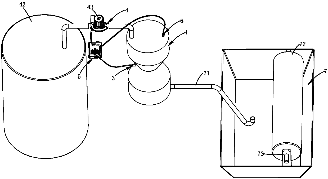
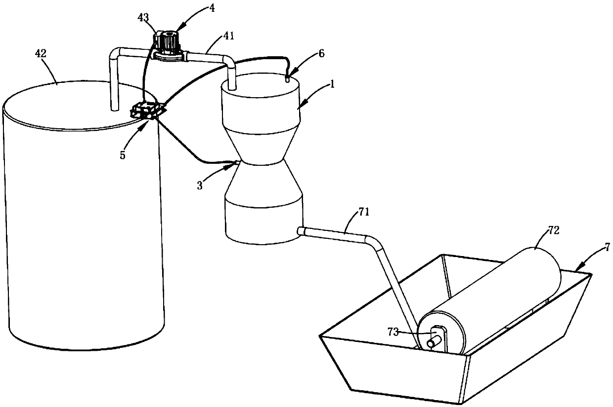
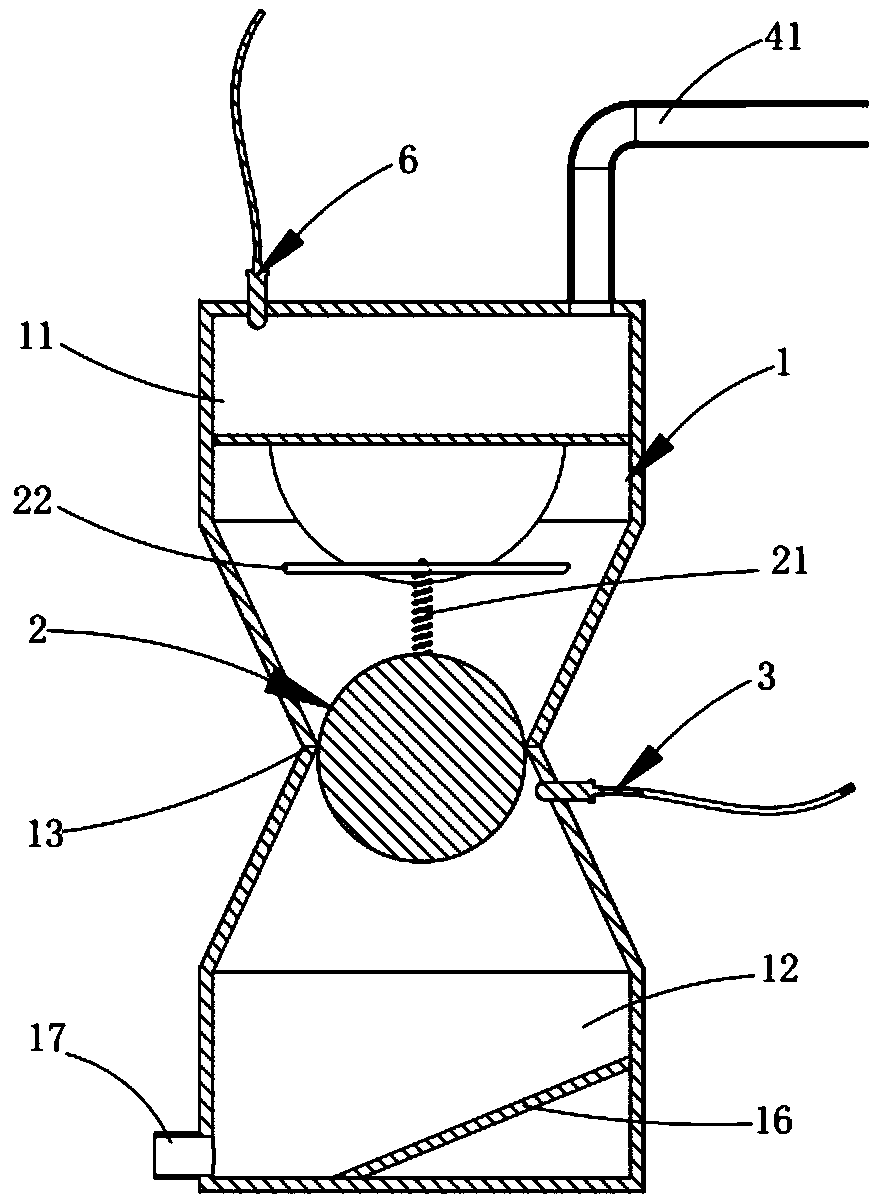
[0031] Such as figure 1 , figure 2 and image 3 As shown, an automatic ink filling mechanism for a printing machine based on a floating ball seal includes an ink bucket 1, a floating ball 2, a position sensor 3, an ink filling mechanism 4, a circuit control board 5 and a liquid level sensor 6, and is characterized in that the The ink barrel 1 is divided into a feeding chamber 11 located on the upper floor and a safety ink volume chamber 12 located on the lower floor, and a neck 13 for limiting the floating ball 2 is arranged between the feeding chamber 11 and the safety ink volume chamber 12; The float 2 is located in the safety ink volume chamber 12, and is connected to the fixed shaft 22 located in the feeding chamber 11 through a pull cord 21. The position sensor 3 is arranged in the safety ink volume chamber 12, and is located in the safety ink volume chamber 12. On the top of the measuring chamber 12, the liquid level sensor 6 is arranged on the top of the feeding cham...

Embodiment 2

[0046] Figure 5 It is a structural schematic diagram of Embodiment 2 of a pruning angle adjustable pruning device of the present invention; Figure 5 As shown, the parts that are the same as or corresponding to those in Embodiment 1 use the reference numerals corresponding to Embodiment 1. For the sake of simplicity, only the differences from Embodiment 1 will be described below. This embodiment two and figure 1 The difference of the shown embodiment one is:

[0047] Such as Figure 5 As shown, a buffer plate 14 is also provided in the charging chamber, and a plurality of through holes 141 distributed in a fan shape are symmetrically provided on the buffer plate 14 .

[0048] As an improved technical solution, arc-shaped deflectors 15 corresponding to the plurality of through-holes 141 are fixedly arranged below the plurality of through-holes 141, and the arc-shaped surfaces of the arc-shaped deflectors 15 completely cover the Several through holes 141 .

[0049] It shou...


PUM


Abstract

The invention discloses a printer automatic-ink-adding mechanism based on a floating ball meal. By utilizing a safe ink chamber arranged in an ink bucket, a printing roller can always run under the situation that the safety ink amount is reserved. When a floating ball located in the safe ink chamber exceeds the detection range of a position sensor, an ink pump receives a sensor signal to automatically add ink, so that the ink bucket retains the buffer ink amount of added ink, and the adverse influence on the printing roller due to non-timely ink adding for the ink bucket is avoided.

Description

technical field [0001] The invention relates to the technical field of packaging and printing, in particular to an automatic ink filling mechanism for a printing machine based on a float seal. Background technique [0002] In the packaging printing process, the ink required for printing is usually supplied and replenished by the oil supply pump, that is, the oil supply pump is set on one side of each printing area to pump the ink to the ink cartridge. If the ink sent into the ink cartridge exceeds a certain Under the influence of the force generated when the printing roller group rotates, the ink in the ink box will fluctuate, and even overflow the ink box, which not only causes waste, but also affects the working environment. On the surface, it will affect the printing quality, and most of the ink adding systems of printing machines nowadays are added in segments, and the ink is added when the ink cartridge reaches a certain position, and the ink cannot be added in time, so...

Claims


Application Information

Patent Timeline
Patent Type & Authority Patents(China)
IPC IPC(8): B41F31/02
CPCB41F31/022
Inventor 许磊
Owner 浙江青联文具科技有限公司
Why Eureka
Try Eureka