An anti-winding crawler drive wheel with track blocks
What is Al technical title?
Al technical title is built by PatSnap Al team. It summarizes the technical point description of the patent document.
A crawler drive, anti-winding technology, used in crawler vehicles, motor vehicles, transportation and packaging, etc., can solve problems such as damage to the crawler structure, hindered driving, and affecting work tasks.
Active Publication Date: 2019-08-23
高唐融知融智科技服务有限公司
View PDF5 Cites 0 Cited by
Summary
Abstract
Description
Claims
Application Information
AI Technical Summary
This helps you quickly interpret patents by identifying the three key elements:
Problems solved by technology
Method used
Benefits of technology
Problems solved by technology
[0002] At present, track drives are used in all aspects of engineering vehicles; the durability of engineering vehicle tracks, the passability of any terrain, and the anti-destructive properties are the main indicators for evaluating the quality of a tracked engineering vehicle; especially when driving in a variety of plants. , Straw that can be wrapped around the wheel or the ground with abandoned steel wires of a certain length, the sharp corners of the track drive wheel will be easily entangled, the light one will cause the drive to be blocked, and the heavy one will damage the track structure and cause greater losses. affect work tasks
Method used
Image
Click on the blue label to locate the original text in one second.
Reading with bidirectional positioning of images and text.
Examples
Embodiment Construction
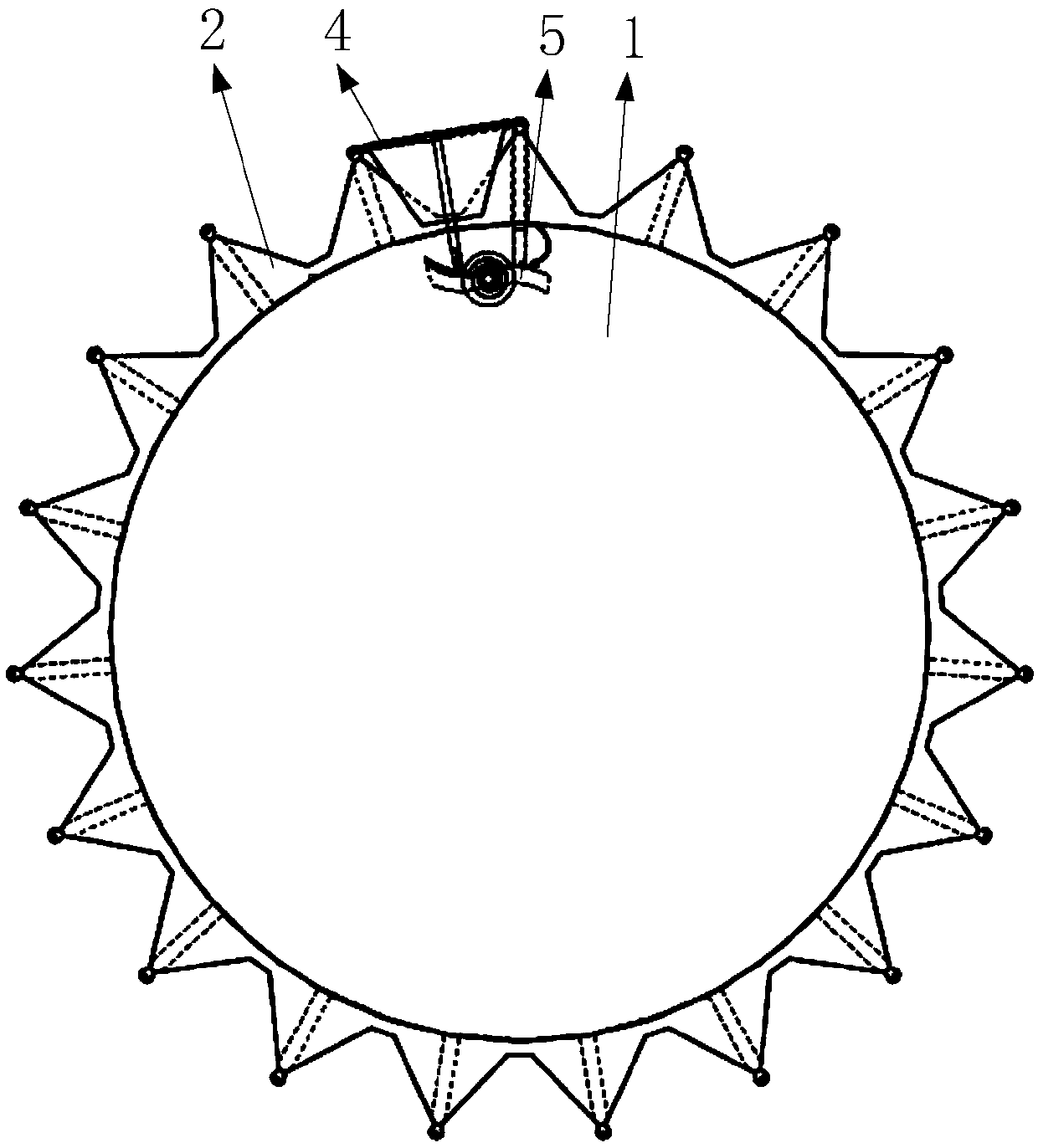
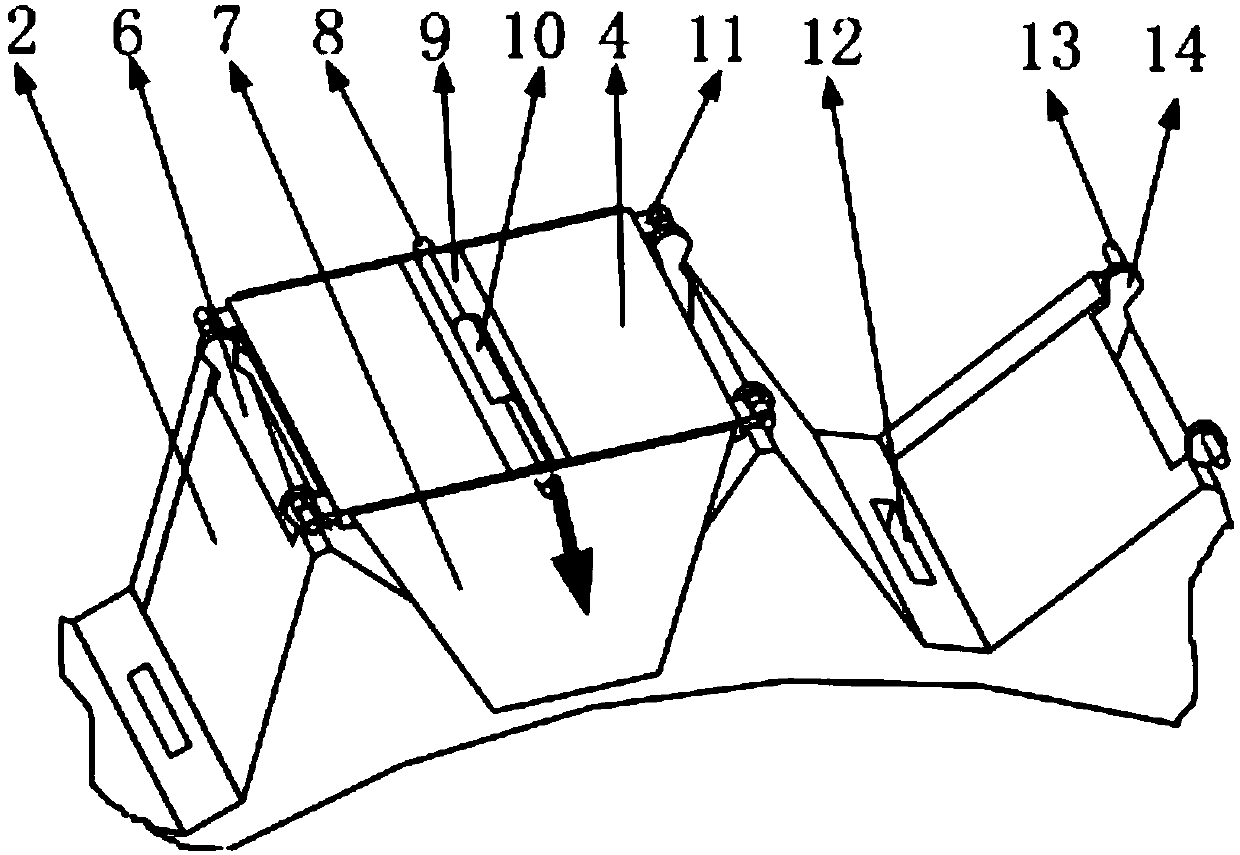
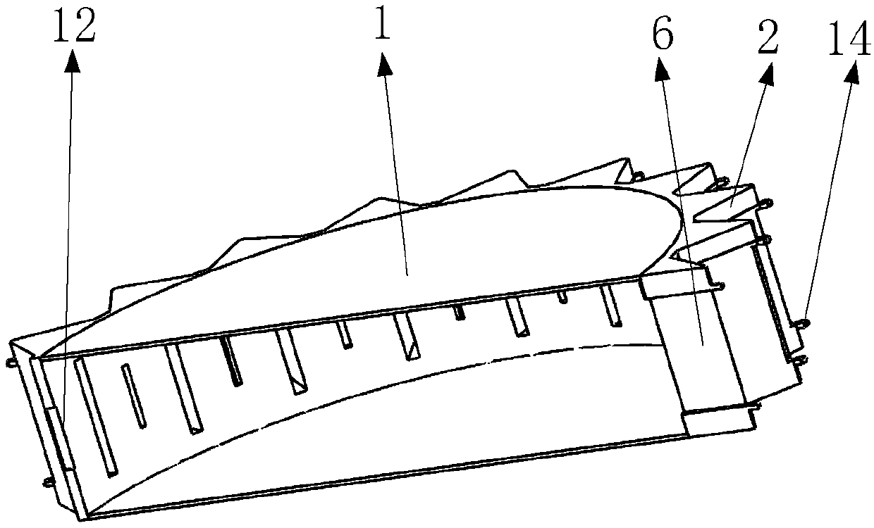
[0028] Such as figure 1 , 2 , as shown in 12, it includes side plates, shells, retaining sleeves, adjustment mechanisms, card channels, side baffles, jacking shafts, top shaft side swivel sleeves, top shaft transfer sleeves, anti-collision blocks, pressure applying channels, and end shafts , end lugs, anti-collision block lugs, retainer sleeve inner groove, retainer inner plate, crawler chain, chain slope, chain top mouth, chain top surface, among which such as figure 1 , 3 As shown in the figure, only a pair of structures at two adjacent sharp corners are shown in the figure, and this structure is distributed between all sharp corners and adjacent sharp corners; the shell is hollow in the middle, and how many A sharp corner; side panels are installed on both sides of the shell, such as figure 2 As shown, an end shaft is installed on both sides of the top of the sharp corner through an end lug, the groove between the sharp corner and the adjacent sharp corner has a pressur...
PUM
Abstract
An anti-wind crawler drive wheel with track blocks, comprising a side plate (1), a shell (2), a retaining sleeve (4), an adjusting mechanism (5), a clamp channel (6), a side baffle (7), a top shaft (8), a top shaft side rotating sleeve (9), a top shaft middle rotating sleeve (10), an anti-collision block (11), a pressure channel (12), an end shaft (13), an end lug (14), an anti-collision block lug (61), a retaining sleeve inner groove (62), an inner baffle (63), crawler chains (65), chain inclined planes (66), and chain top openings (67), wherein the crawler chains (65) are connected by means of rotating shafts to form a crawler belt, sharp corners of the shell are clamped into the chain inclined planes (66) of the crawler chains (65) to drive the crawler belt to rotate; the adjusting mechanism (5) comprises a fixing column (15), a first spring (16), a spiral spring (17), a snap board (18), a rotating mechanism (19), an S-shaped lever (20), a pressure plate (21), a plate spring (49), a plate spring support (50), a snap board rod (51), an external fixing block (53), a sliding shaft (55), a notch (59), an internal fixing block (60), a pressure plate rod (64), a front stroke guide plane (70), a first track block (71), a rear stroke guide plane (72), a second track block (73), and a rear stroke retaining plane (74); the retaining sleeve (4), the inner baffle (63) and the side baffle (7) cover spaces among the sharp corners of the shell and adjacent sharp corners, and the phenomenon that the crawler wheel loses efficacy due to the fact that weed or entanglements are wound around the sharp corners of the driving wheels generally can be avoided; the passibility of the crawler wheel is improved.
Description
technical field [0001] The invention belongs to the technical field of track drive, and in particular relates to an anti-winding track drive wheel with track blocks. Background technique [0002] At present, track drives are used in all aspects of engineering vehicles; the durability of engineering vehicle tracks, the passability of any terrain, and the anti-destructive properties are the main indicators for evaluating the quality of a tracked engineering vehicle; especially when driving in a variety of plants. , Straw that can be wrapped around the wheel or the ground with abandoned steel wires of a certain length, the sharp corners of the track drive wheel will be easily entangled, the light one will cause the drive to be blocked, and the heavy one will damage the track structure and cause greater losses. affect work tasks. So it is necessary to design a kind of anti-winding track drive wheel. [0003] The present invention designs an anti-winding track drive wheel with ...
Claims
Application Information
Patent Timeline
Application Date:The date an application was filed.
Publication Date:The date a patent or application was officially published.
First Publication Date:The earliest publication date of a patent with the same application number.
Issue Date:Publication date of the patent grant document.
PCT Entry Date:The Entry date of PCT National Phase.
Estimated Expiry Date:The statutory expiry date of a patent right according to the Patent Law, and it is the longest term of protection that the patent right can achieve without the termination of the patent right due to other reasons(Term extension factor has been taken into account ).
Invalid Date:Actual expiry date is based on effective date or publication date of legal transaction data of invalid patent.